Index of schematic symbols
Included here are schematic symbols for all the components that we’ll be working with this semester:
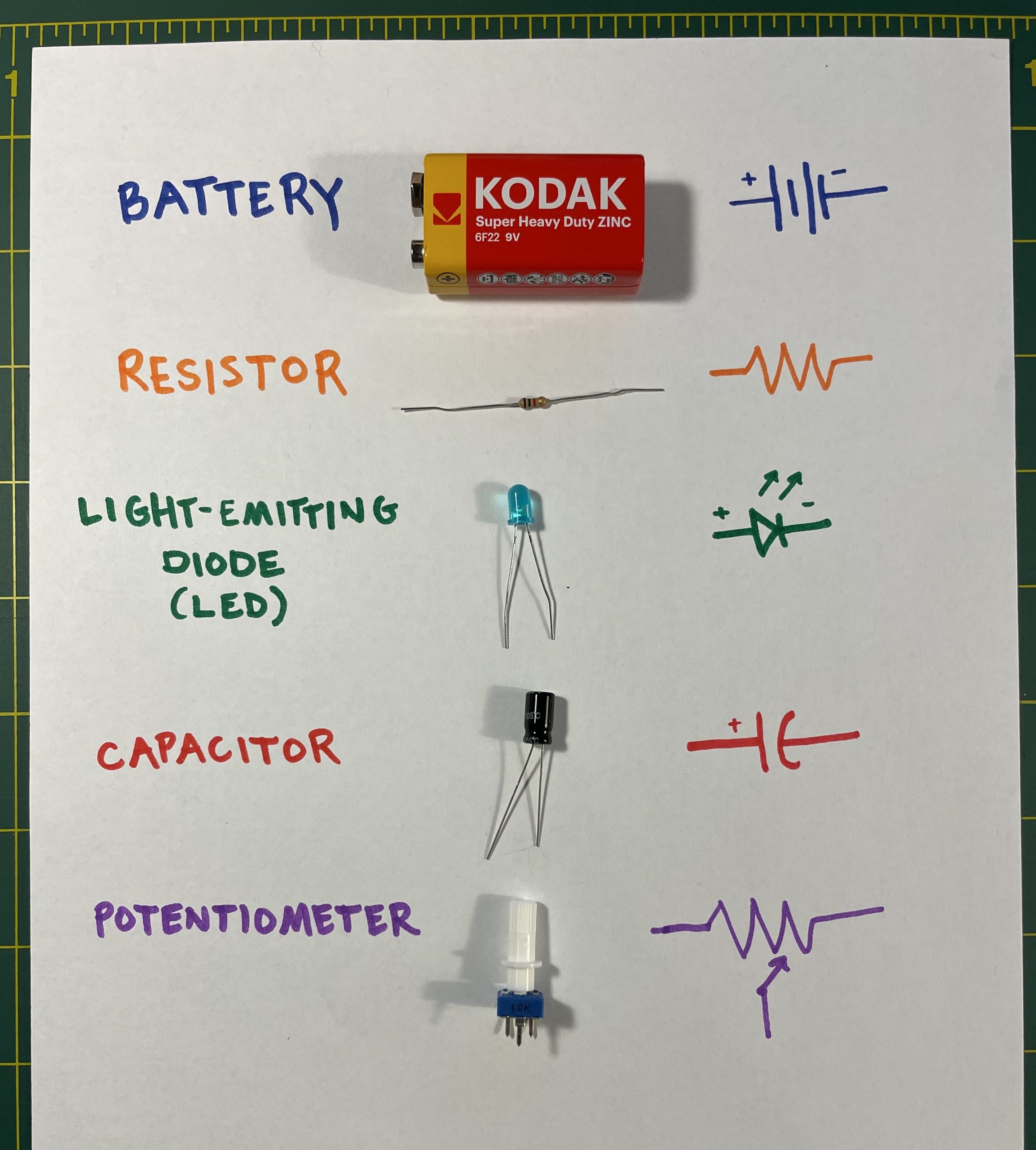
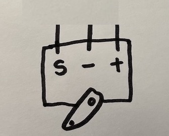
- Battery
- Resistor
- Light-emitting diode (LED)
- Capacitor
- Potentiometer
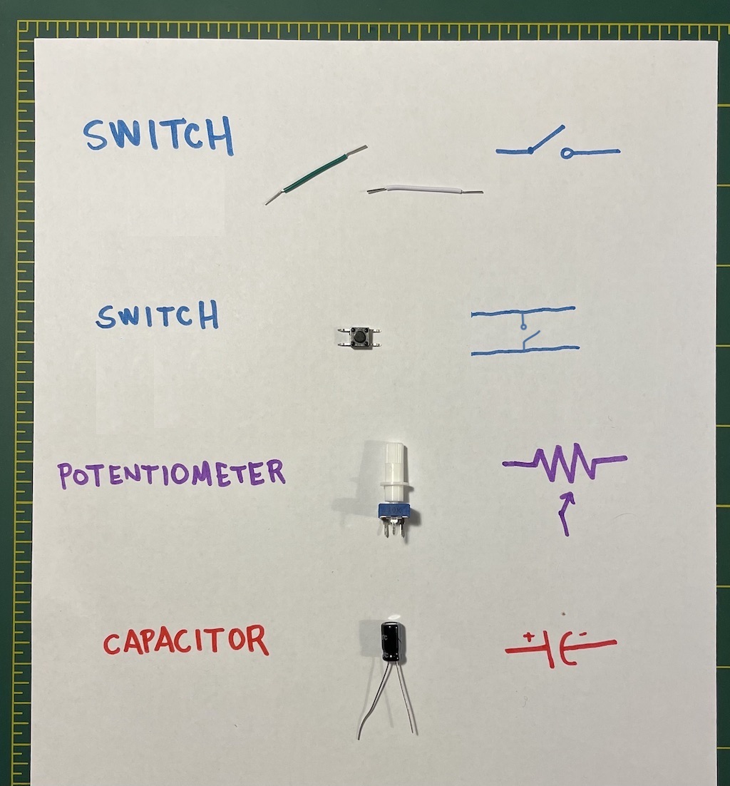
- Switch (x2)
- Potentiometer & Capacitor again
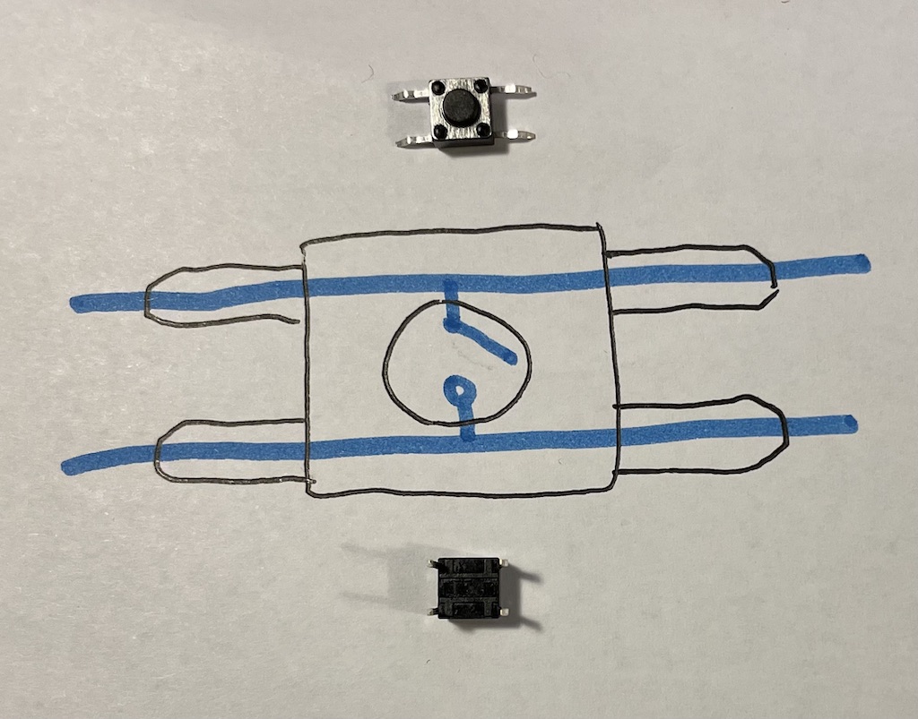
- Detail of DPST button (Switch)
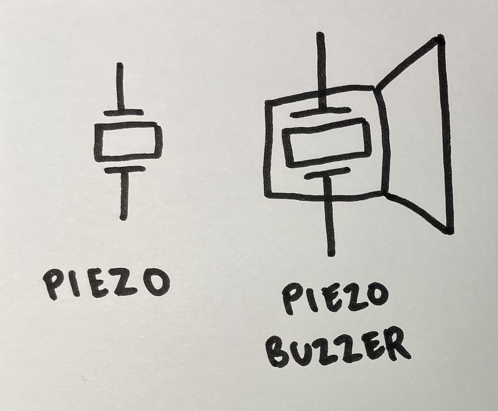
- Piezo element & Piezo buzzer
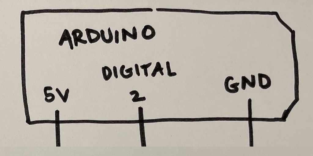
- Arduino board
- Servo motor