Technical Tutorial #1
Recorded video tutorial, searchable transcript with timestamps.
Reading: Selections from chapter 4, “Electricity,” from The New Way Things Work, by David Macaulay. This book is a fun and fascinating introduction to, well, the way things work. It can be a little corny (the mammoths are a recurring motif) but the explanations are lucid and the illustrations can be captivating. Make sure to read pages 256-259, and especially 266-7. Pages 268-9 explain batteries, page 271 solar cells, and 284-5 explain the power generation systems that we’re reading about in Gretchen Bakke’s book, The Grid.
Electricity comes from the movement of electrons through materials known as conductors.
A side note on formatting. Throughout these technical tutorial notes, I will use bold text to indicate technical terms that comprise the discourse of circuit-building. I will define these technical terms explicitly, or implicitly through clear context. Technical work such as this is as much about using the common language & practices of the field as it is the hands-on techniques. These are the terms that you will need to use if you ever want to talk about this work with others. So this semester, these are the terms that we should be using when we speak about project work: in help sessions, in lab notebooks, and with each other.
A conductor is a material made up of molecules that allow electrons to easily move around – this allows them to carry or conduct electricity. A source of electrical power is a displacement of electrons from one material to another. We derive electricity from such a power source by applying a conductor to connect these two materials. Since the conductor allows electrons to move freely, it allows them to return back – effectively rectifying the displacement and achieving a kind of equilibrium. This is called a circuit.
As the name implies, circuits have a circular quality: a sense of closing a loop, allowing electrons to move from a source, through a series of conductors, and back.
Electricity moving through a circuit is commonly understood through a metaphor with water.

In the water metaphor for electricity, the battery is the thing that displaces the water by raising it to a certain height, and the circuit is the pipes and troughs that allow the water to return to its starting point. (Just to be clear: this is a metaphor, a useful model for understanding, but not precisely how electricity actually works; and if we try to stretch the metaphor too far to explain all electrical phenomenon, we’ll quickly reach its limits.)
We measure electricity in several ways. The term you are probably most familiar with is voltage. This is measured in volts, written as V. Just like we measure distance with miles or meters, and weight with pounds or grams, we measure electrical potential with volts. In the water metaphor, this corresponds to the height of the tower. It is like the force. The greater the voltage, the more the electrons have been displaced, and the greater force that exists to bring them back. To give you examples to put this quantity into perspective: a typical AA battery delivers 1.5V, the alkaline batteries that we will be using in our class hold 9V, and a typical healthy car battery will be about 12V.
The other main quantity in measuring electricity is current. This is measured in amps, written A. In the water metaphor, current corresponds to how fast the water is moving.
In the above image, the mill is a like an electrical component that we place in the circuit: it is conductive, so electrons pass through it, and in doing so, they activate the device somehow, producing an effect. In the context of water, the mill might be used to grind wheat into flour or produce paper mulch. In electrical circuits, the components might be a lightbulb, a buzzer, or a motor. These things are arrangements of special kinds of matter that convert electrical energy into something else. A lightbulb is a material that glows when electrified, producing light; a buzzer is a special material that vibrates when electrified, thus producing a buzzing sound; and an electric motor is usually a coil of wires that produces a magnetic field when electrified, which creates motion (usually rotation) in a nearby magnet.
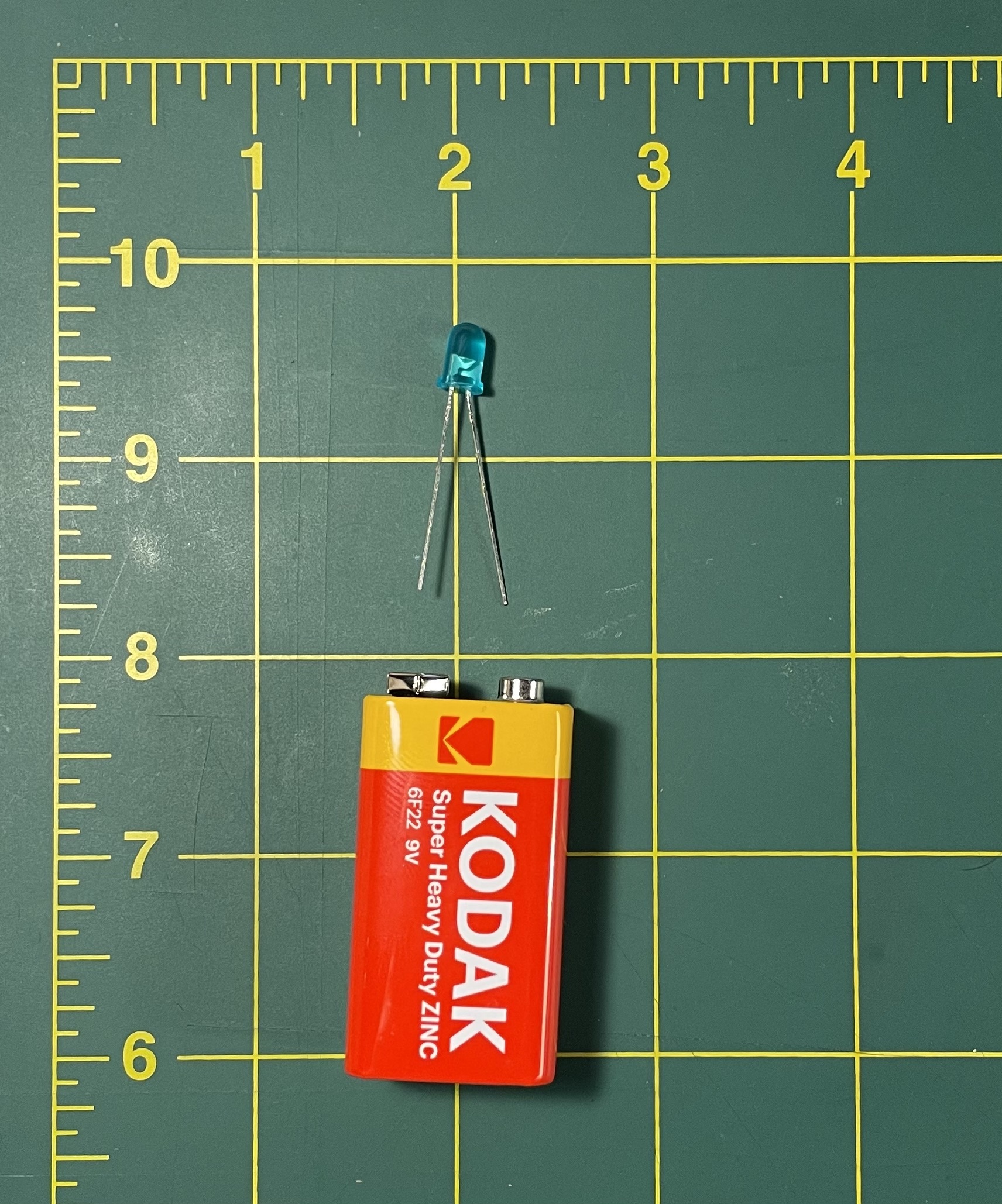
We can make a small circuit by connecting a component to a battery. Here I will use a small, low power lightbulb called an LED, which stands for light-emitting diode. Please don’t actually make this circuit! The 9V battery is too powerful for this LED and will quickly burn it out.
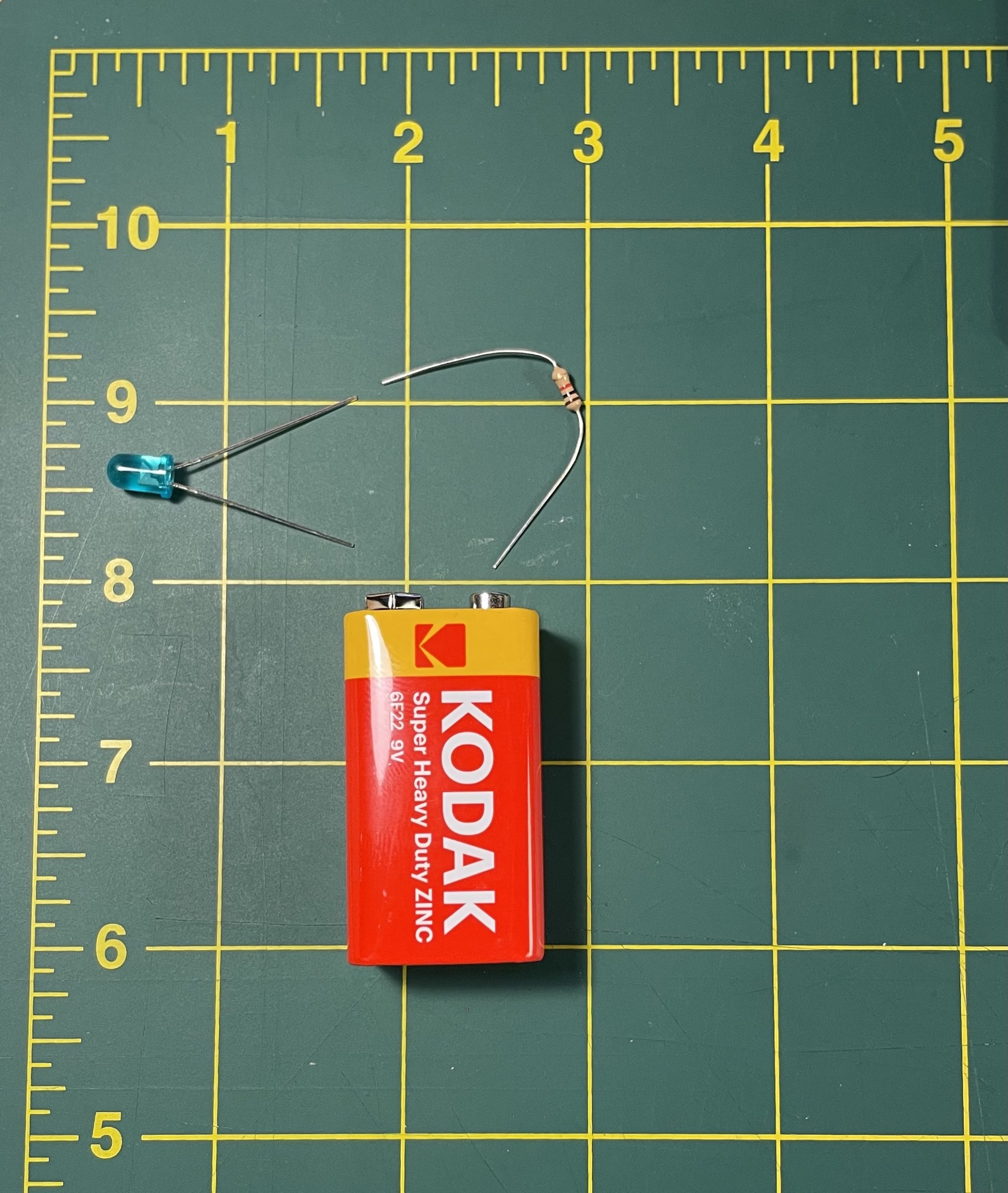
To prevent this burnout, we can add another component called a resistor. In the water metaphor, a resistor is like a valve. A tighter valve will decrease the flow of electricity, while a wider one will impede the flow less. A resistor cannot really increase the flow per se, since all it can do is provide some degree of resistance to whatever current and voltage the source is producing. Every resistor has a certain fixed amount by which it decreases the flow of electricity. This is called resistance and it is measured with a quantity called ohms (named after 19th century German physicist Georg Ohm), written Ω (the Greek letter Omega).
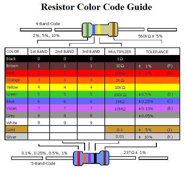
The resistance value of a resistor is usually indicated on the component itself with a very confusing color-coded system. Each band of color on the resistor has a numeric value, and putting these together tells us the value of resistance in ohms. You can use a chart like the following to look up the value of each color:
For example:
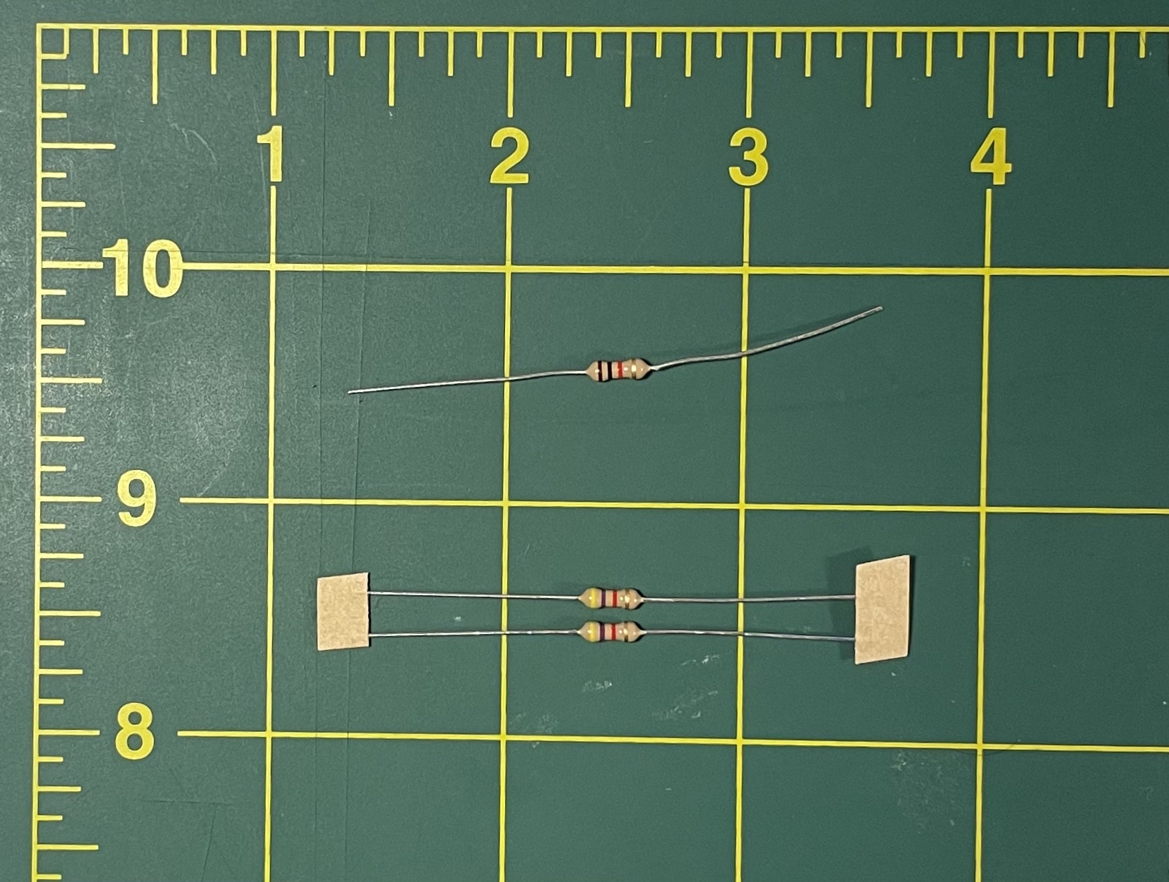
One band of any resistor will almost always be a metallic silver or gold color. This indicates its tolerance, how precise that resistance value is. We can mostly ignore it for what we’ll be doing this semester. But it is useful because the metallic band is always the last number: I’ve oriented the resistors in the above image with the metallic band on the right, and we read the color bands from left-to-right. Both of these resistors have four bands, so in the chart above we use the top mode: “4 Band Code”. For example, with the top resistor, the bands from left-to-right are brown, black, and red (and gold, which we can ignore). Looking those up in the chart corresponds to 1, 0, and 100, so this is a 1000Ω resistor. The first two bands are concatenated together, and the last band is a multiplier. For the bottom resistor, the bands are yellow, purple, red, corresponding to 4, 7, and 100, so this is a 4700Ω resistor.
I find this system to be very frustrating and prefer to simply use a resistor color code calculator like this one – although the truly challenging part about it for me personally is that I can never seem to distinguish red, orange, and brown color bands from each other.
Lab notebook task #1. Go through the resistors in your kit and, using the resistor color code calculator, or if you’d like, doing it by hand with the chart above, catalog the resistors you have and what their values are. Include these in your lab notebook. You don’t have to do all your resistors, but do at least a few.
Generally, increasing resistance decreases current. The relationship between these three quantities is expressed with a simple formula:
V = I x R
Voltage in a circuit is equal to the product of current and resistance. This equation is known as Ohm’s Law. and it describes what is perhaps the most fundamental relationship for understanding the phenomenon of electricity.
An LED is a special kind of a more general component called a diode. A diode is actually not a conductor, but rather is made of a special material called a semiconductor. This is a material that only partly conducts electricity (hence the name). In some cases this means it conducts forward but not backward, or it might conduct forward and backward in one direction, but not at all in a cross direction. Examples of semiconductors include metals like germanium or galena. The most famous is probably silicon. Semiconductors were discovered in the early 20th century and are a key component in wireless communication (which we’ll see in unit 2), transistors, and virtually all digital electronics that followed.
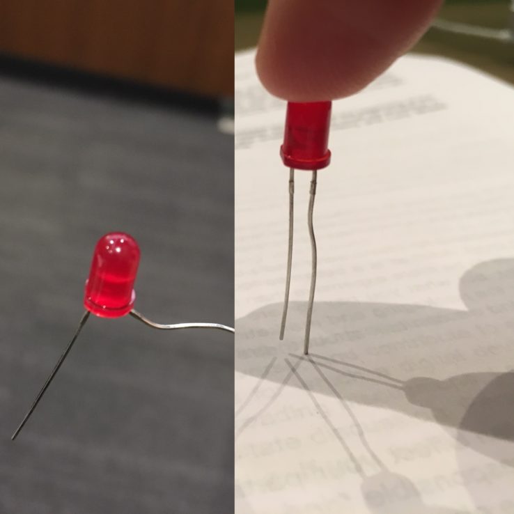
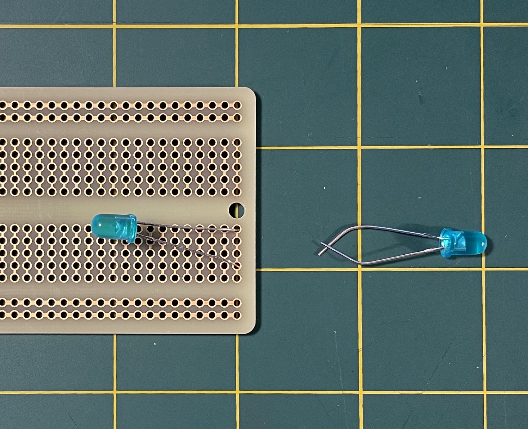
In the case of a diode, a semiconductor has been carefully arranged so that it conducts electricity in one direction, but not backward. In the water metaphor this would be like a one-way valve. For us, this means is that a diode is a directional component: it must be placed in a circuit in a certain orientation. More specifically, the negative end must go toward the negative part of the circuit, and the positive end to the positive part. The negative end of an LED is indicated by a flattened notch and a shorter lead:
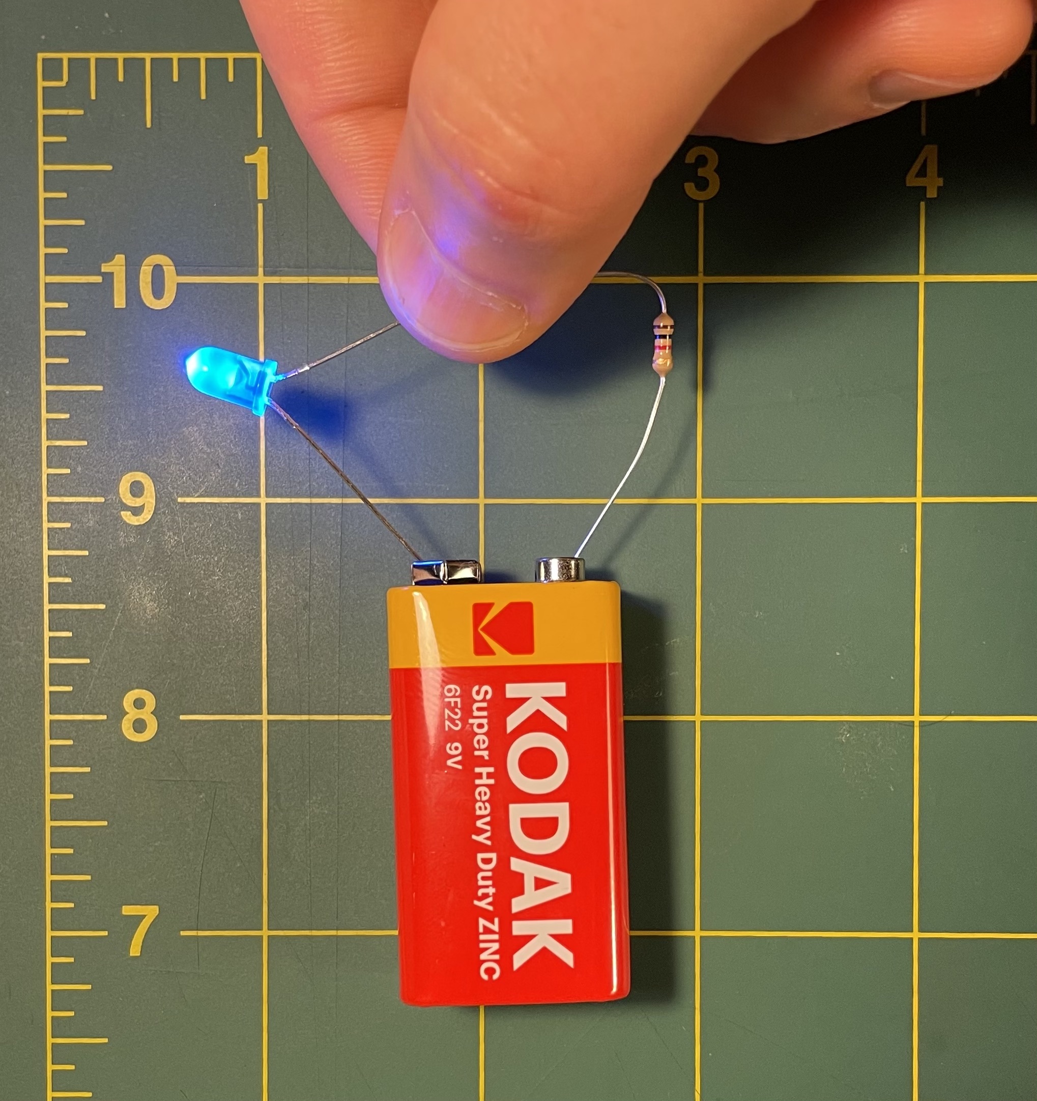
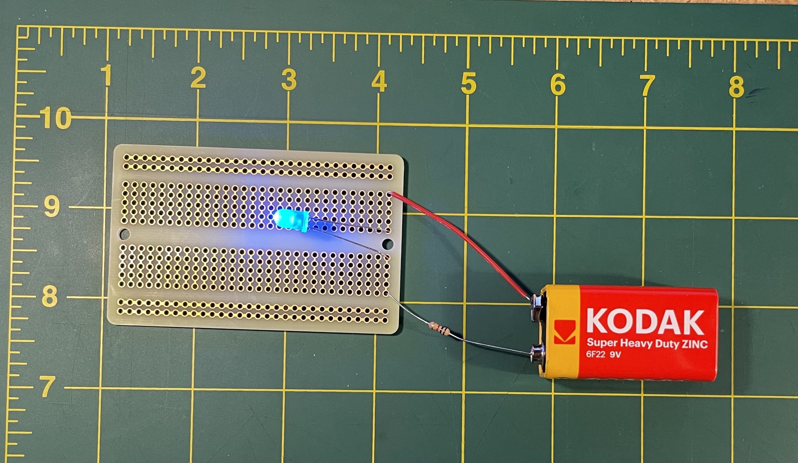
The negative side of the LED must be connected to the negative part of the circuit. Touching the negative side of the LED to the negative terminal of the battery, and pinching the positive end to a resistor, which is touching the positive terminal of the battery, causes the LED to illuminate.
Obviously, this method of circuit building will not get us very far. When building more complicated projects that you are ready to make permanent, you can form circuits by soldering: a technique that kind of welds conductors together to form solidly attached circuits. But for this semester, when working and experimenting, you won’t need to form such permanent connections right away. For this purpose, we’ll use a tool called a breadboard.
To use the breadboard you form circuits by inserting electrical components into the pins (the term for the little holes). A breadboard lets you quickly assemble circuits for testing and experimenting in a way that is stable, but without making permanent connections, so you can easily rework and re-assemble.
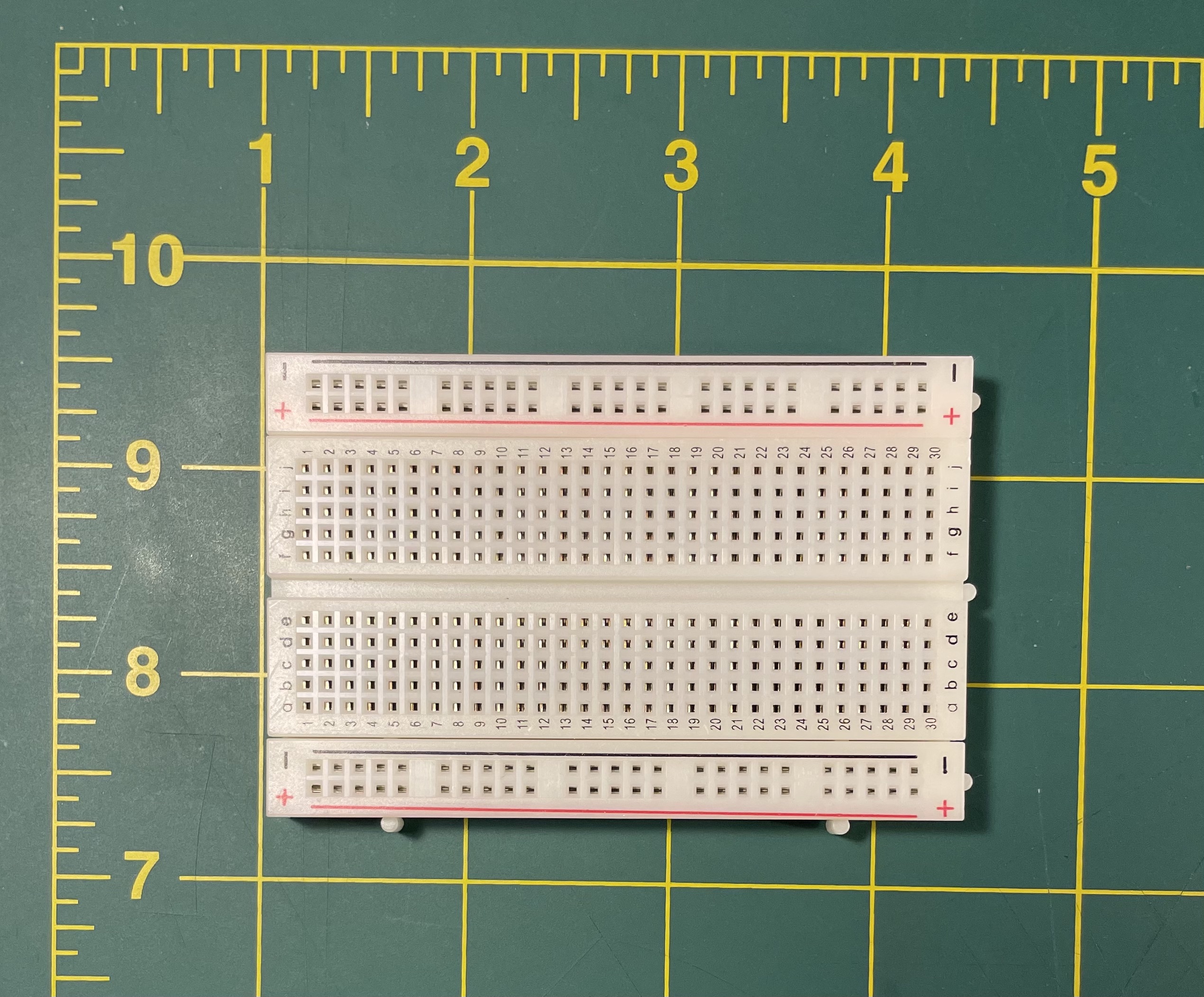
Working with a breadboard can be very convenient and easy. But, it is something that often seems to trip students up. So let’s spend a few minutes talking about how to use this to form connections. If we were to open up a breadboard it would look something like Figure 9:
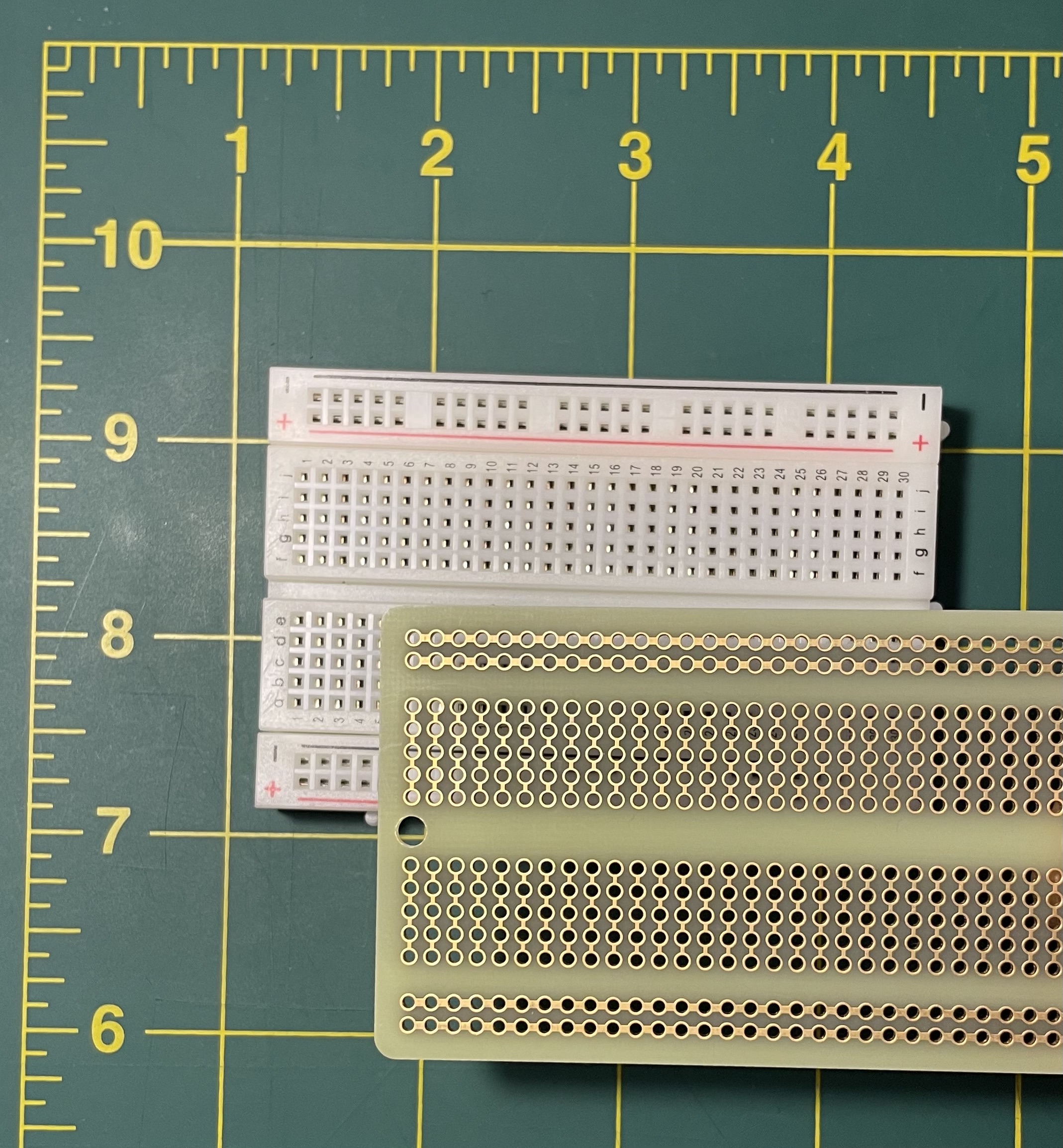
Note the pattern of gold-colored metal. The metal here is a conductor and so acts like a wire, it forms connections. What does it connect? All the pins (holes) that it is touching. If you look at the labels on the breadboard underneath, we might say that “a1” is connected to “b1” is connected to “c1” is connected to “d1” is connected to “e1”. If you put a wire in “a1” and another wire in “e1”, it’s like they are touching – but not “f1”, “g1” etc, since they are not connected by the same metal strip. We use these connections to form circuits.
Putting our basic LED-resistor-battery circuit from Figures 3 & 7 into the breadboard internals could look something like Figure 10. Pay attention to how the metallic strips act like connections, connecting the various wires as I did by hand above. Note that I’ve added an extra write here to connect the battery to the breadboard.
Throughout all you project work this semester, please keep in mind that there is never one single right way to wire up a circuit in a breadboard. There are many, many equally valid options for where to place the pins. It all just depends on what looks clear to you, what you’re working on, how organized & fastidious you wish to be, what will be helpful for you to look at later, and how it all physically fits together.
Common mistake: Never connect a component like I’ve done in Figure 11. Notice how both ends of the LED are in the same row of the breadboard. This would be equivalent to touching the two ends together, like I’ve shown on the right. Doing this is like connecting one end of a pipe to itself. It has no effect. If it is connected to a power source, it might rapidly drain its power.
Putting all this together, we can build our circuit with a breadboard as illustrated in Figure 12. (Often the word “breadboard” is used as a verb, like “google.” So one might say, “I could breadboard circuits all day.” To which one might reply, “Wow, you really like breadboarding.”)
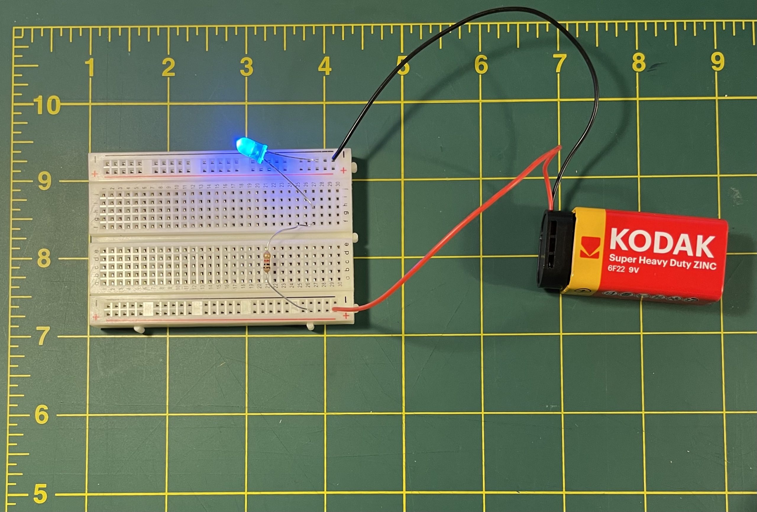
Note that I have added a battery clip here. The battery clip only attaches to the battery one way, and the red wire always corresponds to the positive terminal of the battery, while the black wire usually corresponds to the negative terminal.
Lab notebook task #2. Once you have this put together, try swapping out the resistor for one or two resistors with different resistance values and notice how the brightness of the light will change. Document this in your lab notebook. You can use photos if you’d like, but also use your own words. How would you describe the relationship between resistance value and the behavior of this circuit?
You may also have noticed the small red and blue “+” and “-” indicators on the breadboard. There is nothing special about these rows of pins. Those labels are just there to help you stay organized. The “+” and “-” indicate the positive and negative sides of the battery, so it is a common convention to connect them that way, but there is nothing special or technical about the breadboard to enforce this. This is called a power bus, and it is convenient because it gives you a strip of positive and negative pins running all the way down your breadboard to work with by forming multiple circuits cross-wise. It’s like putting “socks” and “shirts” labels on your dresser drawers. There’s nothing special about the drawers. The labels are just there to help you stay organized. You could certainly swap them, or put pants in either drawer, but then you will just confuse yourself. Conventions are there to help you stay organized. Following them will be helpful!
We describe and plan out circuits with special diagrams known as schematics. With this system, each component has an identifying symbol. A schematic of the above circuit would look like Figure 13.
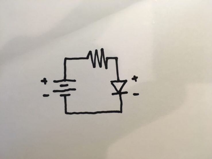
Remember that circuits typically have a circular aspect, or a kind of flow. Reading a schematic, it is useful to find a logical starting point (like say a battery) and reading the schematic from positive to negative along the path that the electrons will take. In this case, starting on the left side and reading clockwise we have: the battery, the resistor, and the LED. Note that the LED’s negative pin is connected to the battery’s negative terminal.
Figure 14 illustrates some other components that we’ll be using and their schematic symbols.
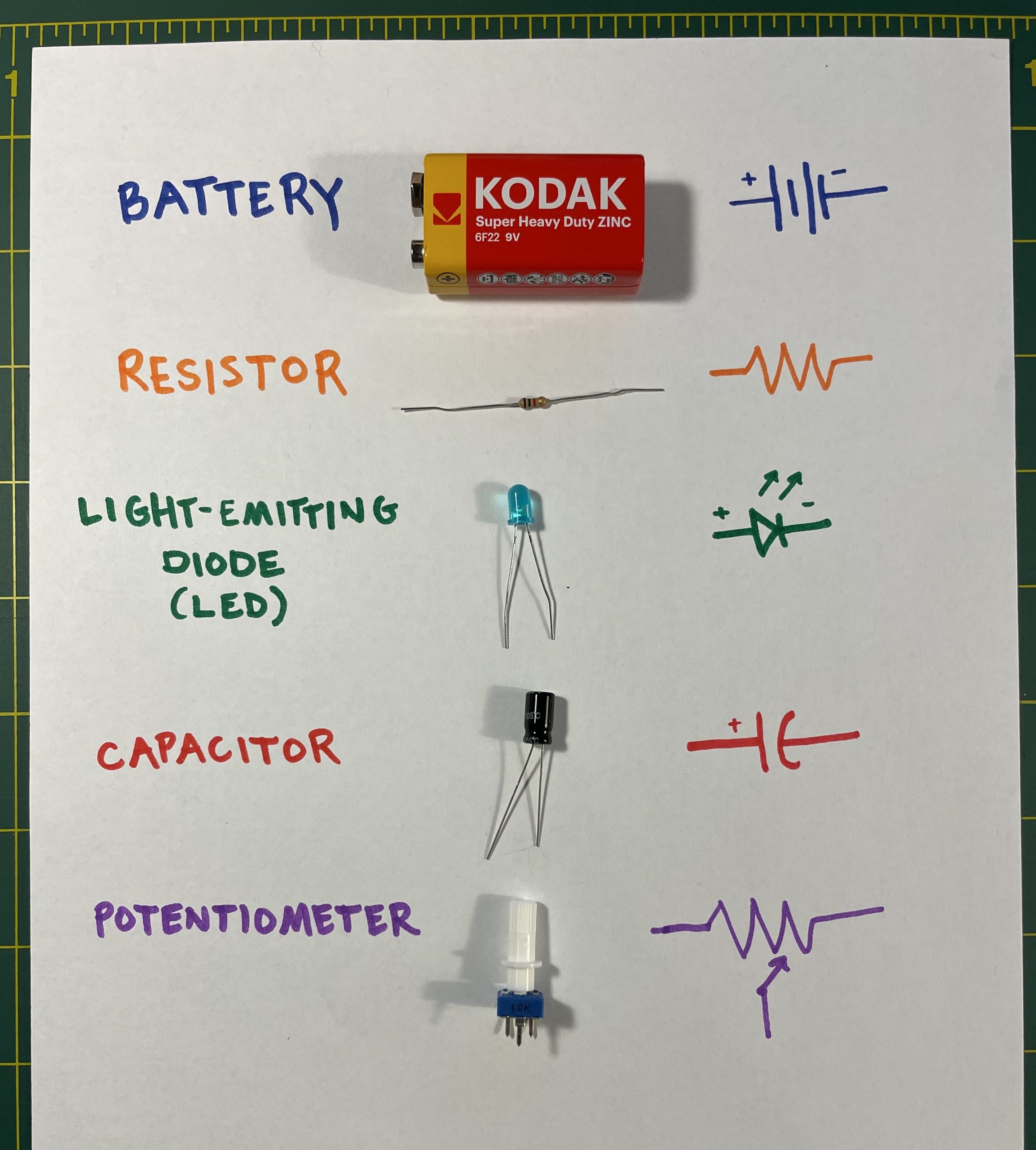
The last item listed there, a potentiometer, is just a variable strength resistor. Try replacing the resistor in your circuit with that (use the middle pin and either side pin), twisting the knob, and see what happens to your LED. Instead of changing resistors to change resistance, we could simply use a potentiometer which allows the resistance to be changed dynamically. Just like a resistor, each potentiometer has a specific resistance value, except that where a resistor had one single resistance, a potentiometer has a range.
Lab notebook task #3. Replace the resistor in this circuit with a potentiometer. Describe what happens.
Lastly, in addition to the terms positive and negative, there are some other terms we will commonly use to refer to the different parts of a circuit. All the terms in the right column are not precisely synonymous, but I will generally be using them approximately synonymously to refer to the positive parts of a circuit. Similarly, the terms in the left column are don’t always mean precisely the same thing, but will generally be used to refer to the low parts of a circuit.
| positive (+) | negative (-) |
| HIGH | LOW |
9V (or, when working with Arduino, 5V) |
0V, GROUND, or GND |
Investigating circuits
The primary tool used to debug circuits is called a multimeter – so named because it is one tool that can measure (meter) many things (multi). If you have done any programming, you have used a debugger, or various commands to display variable values (usually called something like print() in most programming languages). In working with circuits, we don’t have such tools, but the multimeter is the closest thing. A multimeter allows us to investigate, probe, and ask questions about the values of various parts of a circuit in terms of volts, amps, or Ohms.
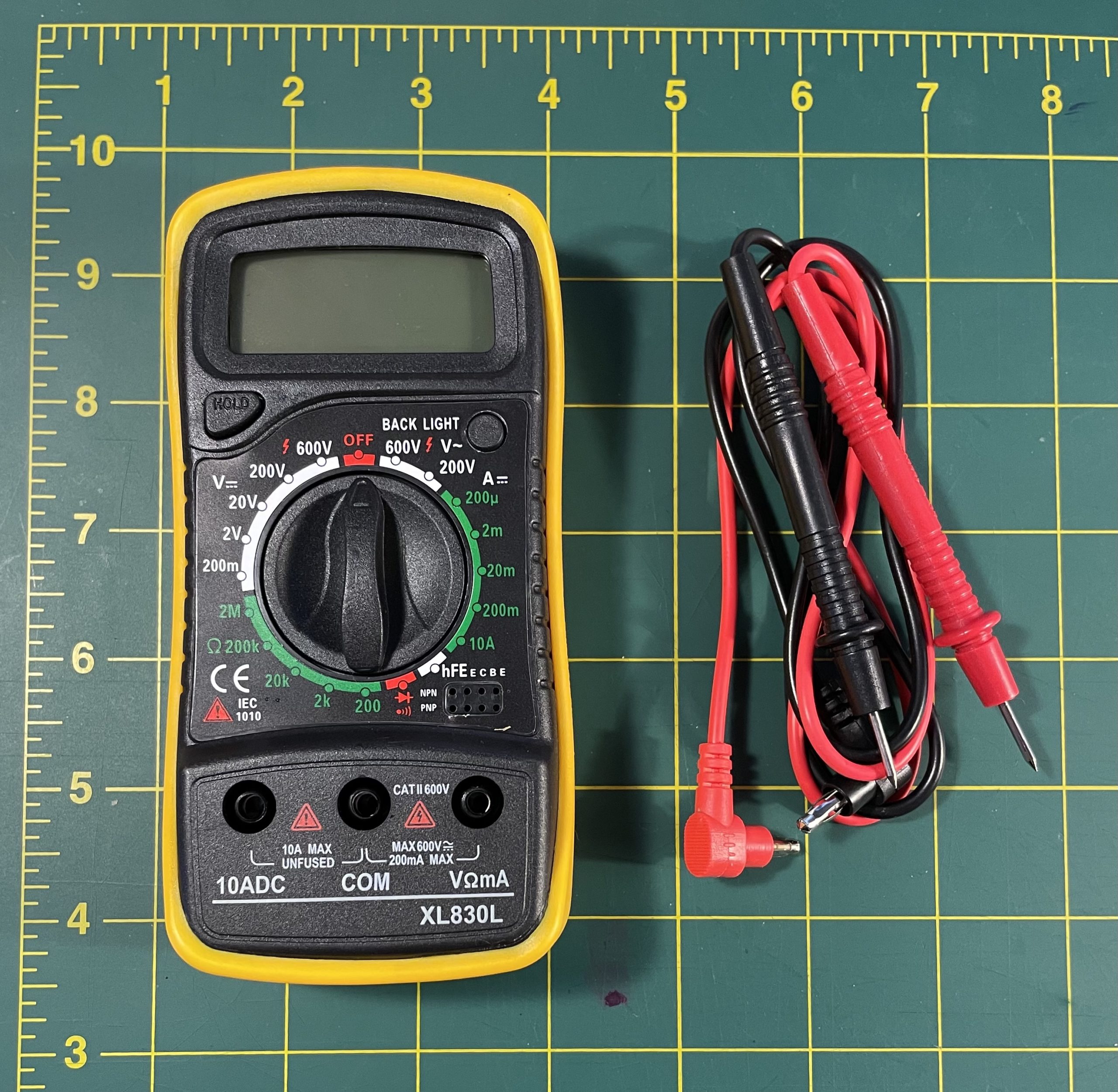
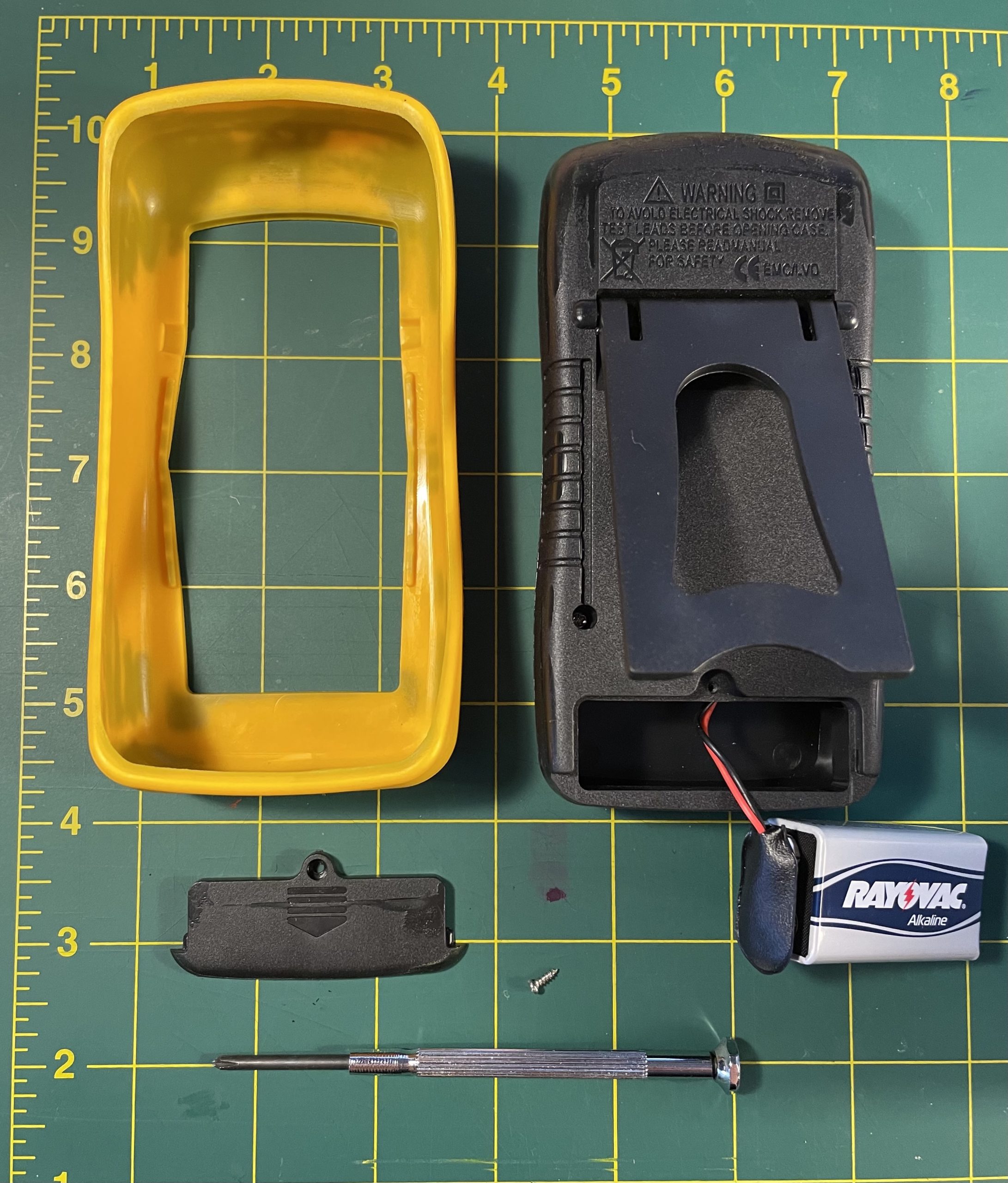
The multimeter that came with the Arduino Student Kit looks like this, and requires you to add a 9V battery. Most multimeters will almost certainly require you to add a battery through a similar process. If you don’t have this type of small screwdriver, you can try using the screwdriver for glasses repair, or perhaps improvise with another object you might have around the house that you can enlist for this purpose.
To use, connect one probe to the “COM” socket, and the other probe to the socket that says “VΩmA”. In general, the convention is to use the black probe for “COM”, which is similar to the GROUND part of a circuit, and use the red probe for the other.
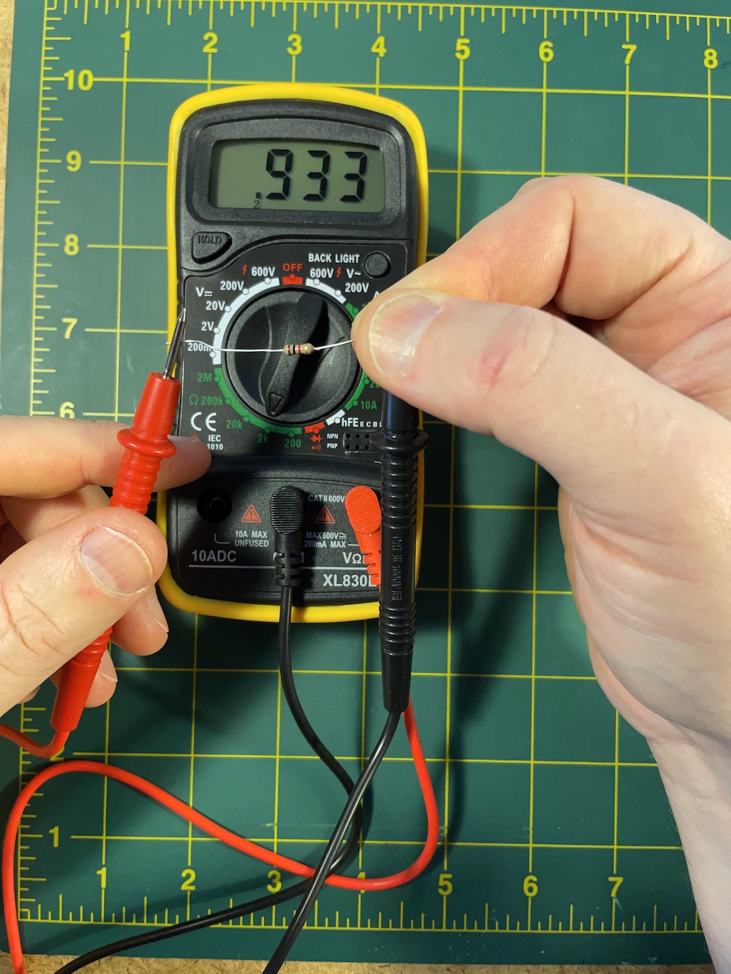
To test a circuit or a circuit component for various values, you need to adjust the multimeter function with the big twisty knob which is the device’s primary user interface. Move the knob pointer in the area indicated by Ω to test for resistance. This will send a small voltage through the object that you’re testing, and read how much resistance it adds. The number on the dial is the maximum allowable measurable value, and also the scale in terms of which the display will read. In the picture below, I’ve selected 2K, meaning 2000, and my reading is .933 for a 1000Ω resistor. Since my knob indicates the units are in the thousands, a value of 1 means 1 thousand. If I had dialed it up to 20K (20,000), this resister would have displayed something like .0933Ω. Similar for voltage: dial the knob into the area indicated by a V (use the V with the straight line, not the wavy line which means to use DC, not AC – we can talk about what this means later). Similarly, the scale you select indicates a maximum value and the units with which your results will be displayed.
Since resistors are not directional components, it does not matter which side is connected to red and which to black. But if you want to measure the voltage of a battery, make sure red is connected to the positive terminal and black to negative terminal. Similarly, if you wanted to measure the resistance of an LED, you would need to make sure your direction is correct: black to negative, red to positive.
Lab notebook task #4. Get your multimeter working by adding a 9V battery to it. Connect the black probe in your kit to “COM” and the red probe to “VΩmA”. Adjust the dial to “20V” and measure some batteries, touching the black probe to the negative end and the red probe to the positive end. Batteries have advertised values. But what values do you actually find? Next, adjust the dial to “20k” in the “Ω” section. Measure the resistance of some of the resistors whose values you determined in part 1 – are your initial determinations consistent with the multimeter reading? Last, find some objects that you think might be conductive (like a wire, a spoon) and touch the probes to the conductor at varying distances apart. What resistance values do you read? Document this experiments in your lab notebook entry.
Conclusion
Hopefully a few things have already started to become apparent. We often think about electricity and electronics (and especially digital electronics) as being clean, precise, hermetically sealed, not messy or dirty, and having values and effects that operate in an almost immaterial way. We might say they embody grid-like qualities in many ways that we’ve talked about: they operate in accordance with regular, standardized (and standardizing) modes that we might call infrastructural.
But already we’ve can see that we need to throw all that out right away. Underlying all this circuitry is always the need to contend with messy materials and chemicals. Batteries are full of acid, different metals and materials conduct electricity differently, their performance changes at different temperatures and conditions, voltages are imprecise, wires break, connections corrode. The fact is that immense amounts of work and scaffolding go in to producing error controls, tolerances, and the perception of stability in these messy agglomerations of matter, especially to achieve the levels of precision that we call digital. Perhaps digital media is always already off-the-grid by its nature.
Originally when semiconductors were discovered, users had to putz around with wires trying to find conductive strands in hunks of germanium and galena, because no one knew precisely how they worked. Now we can buy a 25¢ diode with a precisely calibrated semiconductor in it.
Why?
What is the significance of this material to grids, or getting off grids – or of digital technology in relation to any of this? There are three connections that I hope you will be able to make here:
(1) As we have been discussing, probably the primary definition of “the grid” is in reference to the electrical grid. This lesson will help you understand some of the fundamental principles of electricity: how it is generated, how it is managed. This will hopefully offer you some new insights as you continue to reflect on the Gretchen Bakke book (The Grid) that we read this week
(2) As we think about grids and getting off them, understanding the actual values at play in circuits will hopefully illustrate that electricity, electrical components, and circuits are always messy, material processes. Their values are never clean and perfect, but always approximate. Precision within these devices comes from carefully managed standards and thresholds. The grid sets on top of its opposite, and is imposed upon it. Think about this in relation to some of the figures from Vannini & Taggart as they negotiated energy fluctuations and the messy processes of energy production in their homes.
(3) As we have seen with many of the off-gridders that we’ve already been studying, they are often very concerned with digital devices in the form of sensors, channeling flows of power (electrical and others), and an almost cybernetic concern with managing various circulations of their lives. The principles here are laying the groundwork for us to think about how to build devices that can do the type of sensing and automation so crucial to that style of off-grid living. The Arduinos that we will learn how to use are often used to implement these kinds of sensor networks. They are programmable, digital devices, but they are able to operate with batteries, in small weather-proof boxes, and in low power contexts. In other words, they are precisely one way to get digital media off-the-grid.
Homework
Find your folder in the Student work folder in Google Drive (also linked from “Class Resources” in the main site menu). Inside that, create a new subfolder named “Project 1”. Next, create a new lab notebook entry: open the lab notebook template (also linked from main menu), make a copy of this file, name it with the date of this workshop (e.g. “Project 1, Tutorial 1, Feb 17”), and move this file into your “Project 1” subfolder. NOTE: Please take care to follow this organizational scheme precisely. If I cannot find a clearly labeled lab notebook document for each technical tutorial, you may not get credit for your work.
Throughout this tutorial, there are four instructions for you labeled “Lab notebook task.” Work through each of these, documenting your work in your lab notebook. You can use photos or videos to document your work, but you should also use your own language – imagine that you are a scientist doing experiments: observe and narrate the results. In your notebook, try to link this back to any readings that we have done this week or earlier, in particular, think about concepts around electricity in the Bakke book. (For example, she mentions potentiometers on page 39!)