Technical Tutorial #2
Recorded video tutorial. I had some technical difficulties with this one. The little box with my head is missing at first which isn’t much of a problem and I fix it a few minutes in. There are also moments when the video seems blurry but it always rectifies itself quickly enough to make the text and images readable. Most crucially, my mouse pointer was not captured by the Zoom recording! Not sure why. There are several points in the lesson where I was using the mouse to point at things on screen, so these will seem confusing now. This will probably be most frustrating around minute 50 when I’m talking about the capacitor circuit (Figure 15) so please just try your best to follow the explanation. Sorry for the confusion and thanks for your patience!
Searchable transcript with timestamps. This transcript is embedded in the video on Google Drive, so if you watch with the Google Drive player, you’ll have closed captions. You can click the “CC” icon to turn captions on/off if they’re getting in the way of seeing the circuit. If you download the video you won’t have captions. I include the transcript here separately to aid people for whom this is a preferred mode to engage. The transcript is searchable with timestamps, so one way to use them might be to skim through or search for a particular phrase (⌘F on Mac, CONTROL-F on Windows) and then jump to that moment in the video if you’d like to watch the explanation. (Timestamp format is HOURS:MINUTES:SECONDS.milliseconds.)
Brief review
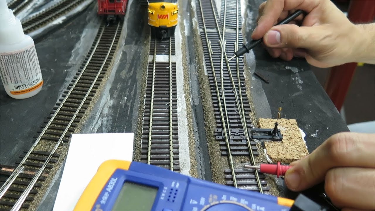
Last week we did an introduction to electricity and the basic principles of building circuits, like voltage, current, and resistance. We talked about the idea that circuits have a circular aspect: they form a kind of loop, from the positive part of a power source to the negative part (with batteries these are called terminals). We discussed the water metaphor for electricity: an imperfect but very useful model for understanding the flow of electrons through conductors and electrical components like resistors and LEDs. And we started working with the multimeter as a tool for examining circuits. If any of that is still confusing, refer back to last week’s class notes and video.
This week we’ll start experimenting with electrical components that change how circuits behave, and we’ll see some circuits with more than one pathway for how electrons can flow through them.
Looking ahead, next week we’ll continue working with these interactive components by connecting them as inputs to programmable Arduino boards.
Components
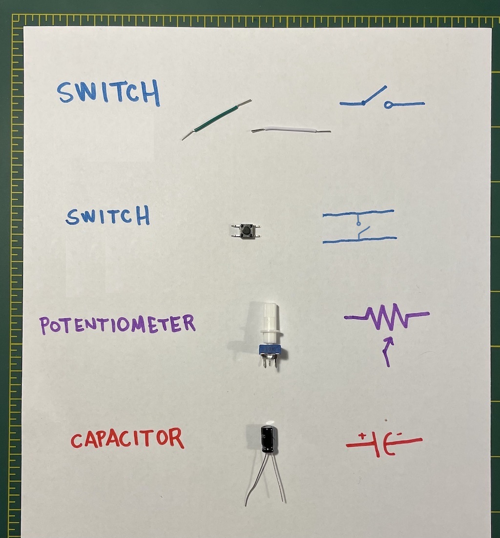
Today we’ll be work through some examples using three components: on/off switches; potentiometers, which allow a gradual range of current; and capacitors, which temporarily store small amounts of electrical charge.
On / off circuits: open / closed loops
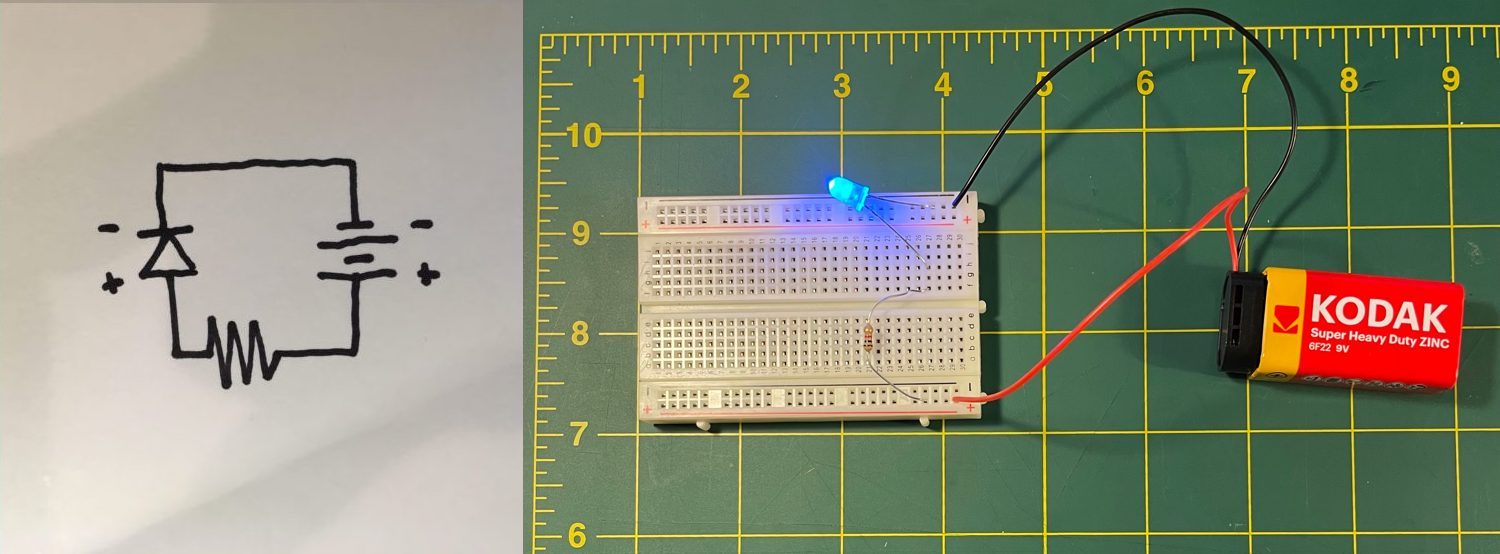
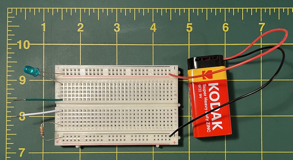
Last week we assembled our first circuit of the semester: a basic loop of battery-resistor-LED. Let’s start this week by picking up where we left off and recreate it.
Two things to note:
(1) In the image above I rotated the schematic from last week so that it better aligned with the image of my circuit. As pictured here, the battery is on the right with the positive terminal on the bottom (the red wire in the photo, the “+” in the schematic), and the resistor is on the bottom as well. It’s important to understand that I didn’t need to do this. Schematics don’t show us precisely how to build the circuit; rather they are diagrams that illustrate the relationships of all the components in the system. But I re-oriented it here in case it is more clear as you’re learning.
(2) Last week I was not fussy about specifying exactly which resistor you needed to use in this circuit. In my case I used a 1000Ω resistor (brown, black, and red, pictured above). There are times when we will need to be precise about which resistors to use and other times when we can be approximate. In this case, I assumed people would use whichever resistor they felt like, and I hoped we might see some different behaviors. In preparing your lab notebook entry you hopefully noticed that larger resistance values correlate to dimmer LED light, and thus lower current. (Remember V = I x R)
Let’s build on that basic circuit by adding a bit of interactivity to this circuit. We’ll do this by adding a very basic switch. A switch is an electrical component that can connect or disconnect the flow of electrons in a circuit, interrupting the electric current or diverting it from one path in the circuit to another. Switches are often electromechanical, and the “mechanical” aspect here refers to physical motion; so a switch is often something that involves a physical component of some sort to affect a circuit. A common light switch is a classic example. Switches can also commonly take the form of simple buttons and other devices. Your kit came with some switches, and we’re going to experiment with some different improvised switches from other materials.
There are several ways to describe and classify switches. One way is in terms of pole and throw. Think of poles as different, independent circuits that the switch activates when it is connected. Think of the throw in terms of the number of activated positions that the mechanical part of the switch can be in. So a standard light switch with one light and an on/off position would have one pole and one throw, which is called SPST for single-pole single-throw. Imagine that this light switch didn’t have an off position but instead when flipped down, it would activate a different light. We’d probably call this SPDT for single-pole double-throw because there is one circuit (one source of electricity) but two positions in which the switch was activated. Here’s a real example of an SPDT switch for sale from adafruit.com. Conversely, imagine a light switch with a regular an on/off position, but when on, it would activate two lights, or two different devices, possibly from different energy sources. This would be an example of a DPST switch, for double-pole single-throw.
The switches we’ll be working with are probably all single-pole, but you may encounter (or create) switches with more than one throw.
Let’s start by adding an SPST switch to our basic circuit, as diagrammed by the schematic in Figure 3.
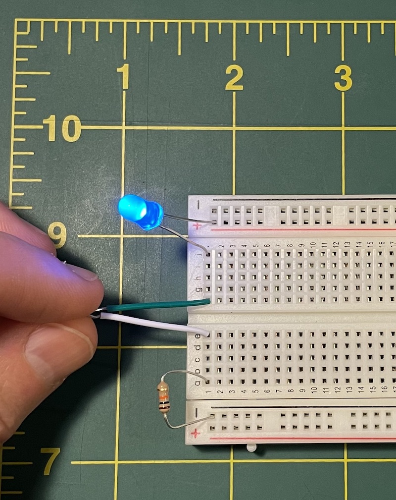
We can start by implementing this in the most basic way possible without even using a proper switch, but simply by using two wires.
When a switch is disconnected, not allowing current to flow, we say that it is open, and when the switch is activated and allowing current to flow, we say that it is closed. Thus the basic two-wire “switch” in Figure 4 is open, and you can close the switch simply by touching the wires together as in Figure 5.
This leads to some additional terms for categorizing switches. Normally-open means that the switch is disconnected by default; and normally-closed, meaning that the switch is connected by default and disconnected when activated. The switch that we’ve just created is also described as momentary, meaning that it is only closed while it is being pressed. This is opposed to other types of switches – often called toggles, latches, or on/off – which can be clicked into place and will hold their position.
Putting this altogether, we can say that our improvised switch in Figures 4 & 5 is a momentary, normally-open SPST switch.
Lab notebook task #1: We are surrounded by electrical devices, meaning then that we are also surrounded by switches of all time. Look around you, in your home or neighborhood, and identify some switches. Include photos of them in your lab notebook and describe them using the terminology above. Additionally, think about them in the context of our class: would you say that they are “on the grid”? If not, what type of energy source do they regulate? i.e., disposable battery, battery that is rechargeable from a wall outlet, a renewable energy source, something else?
Lab notebook task #2: Get creative with an SPST switch. As I’ve shown here, a momentary, normally-open SPST switch can be as basic as two wires. What other type of creative technique can you come up with to create a switch of this type? Use some other objects that you have around you. For example: you might tape longer wires to two piece of aluminum foil; you could tape the wire ends to a cotton swab or other soft object to great a squeeze ball; or perhaps you could attach the wires to a binder clip, a door, a box, or some other object so that your light indicates whether that object is open or closed. Include a picture or video in your lab notebook and describe what you did.
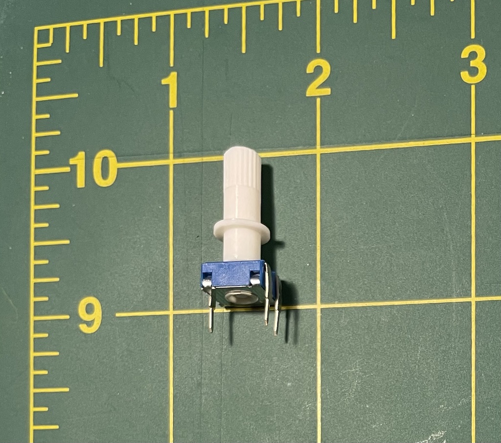
Let’s make a switch that is more interesting than just two wires. Your kit includes a small button, which probably looks like Figure 6.
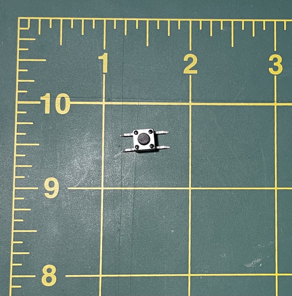
This button might be deceiving. Examining it, you might notice that it has four wires (four leads) and surmise that it is likely a double-throw button. This would mean that by pressing the button, you would be closing two independent circuits. But that is not the case! This can be a little confusing. Probably the best way I can explain it is with a diagram. Figure 7 illustrates a kind of schematic that shows how this button operates.
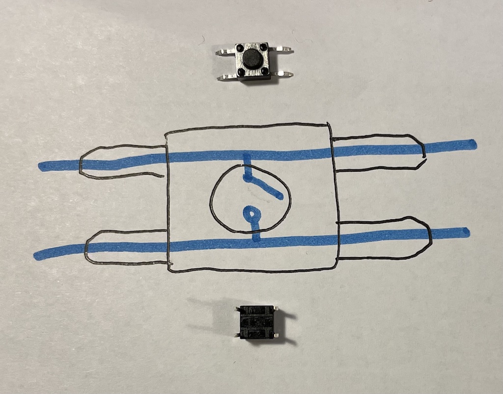
Here you can see how the two wires on top are always connected to each other, and the two wires on the bottom are always connected to each other as well. But as a momentary, normally-open switch, the top pair of wires is not connected to the bottom pair unless the button is being held down. You have to pay careful attention to how the leads are flat to make sure you can distinguish this. If you ever forget, you can turn it over and the plastic markings may help indicate which the connected pairs are.
Figure 8 shows how to add this to our circuit in place of the improvised two wire “switch”.
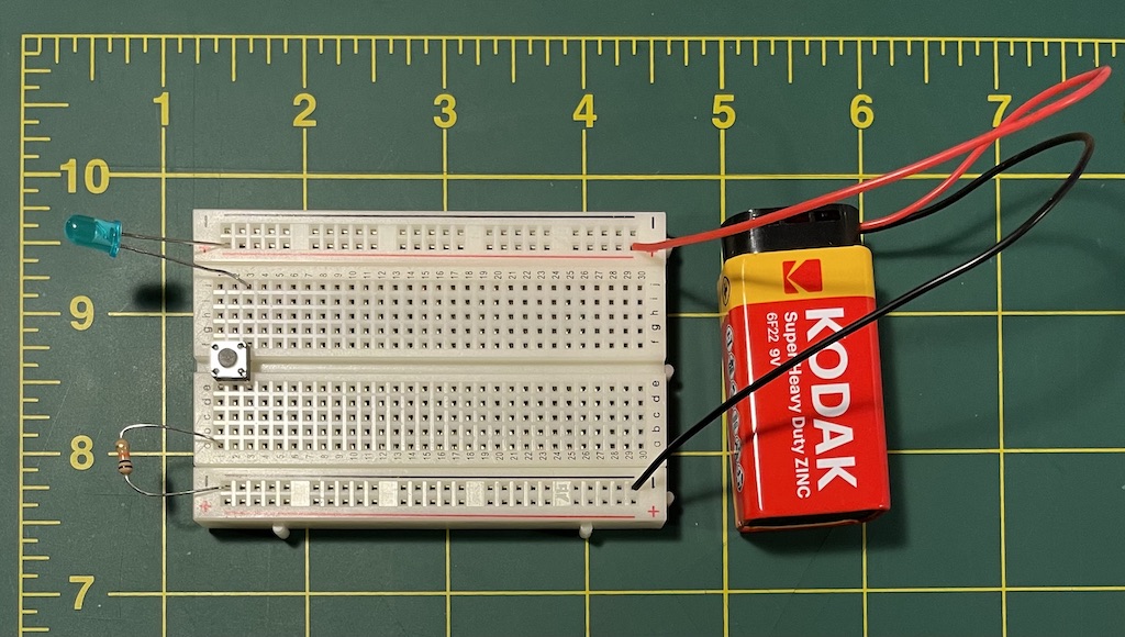
Pay careful attention to the orientation of the button. Fortunately, it only goes in across the breadboard center divider in one way, which is convenient. Note that now my resistor is connected to one side of the button using what Figure 7 called the “top” pair of wires, and the LED is connected to the other side of the button using what Figure 7 called the “bottom” pair. Now when you press the button the LED should go on – and give a nice, satisfying click!
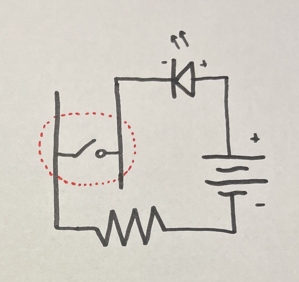
Figure 9 shows the schematic for the circuit we just built in Figure 8. Notice that this is almost identical to the schematic from Figure 4, but with the simple two wire SPST switch replaced with this one from our kits.
Some of the info here was cribbed from ladyada.net, which you may also find helpful. And adafruit.com has a wide assortment of many fun buttons for sale, which you might be interested in for the project.
Lab notebook task #3: Connect at least three buttons, each controlling a different LED. Show your work in your lab notebook. You may wish to use the same resistors for each button/LED in your circuit. The 560Ω resistors could work well here (green, blue, brown). Or you can use different resistors and even use an assortment. Tip: Remember what I said in last week’s tutorial about using the power bus: the strips along the sides of your breadboard. If you connect the positive terminal of your battery to one long row of your breadboard, and the negative terminal of your battery to the long row on the other side of the breadboard, you can make your resistor-button-LED circuits going across the breadboard at three locations.
From digital to analog
Within media studies in general, and digital media studies in particular, one of the long-running discussions is around difference(s) between analog and digital. Most generally, digital is thought of as operating on the symbolic and discrete, while analog is thought of as operating on correspondence and the continuous. Let’s illustrate that dichotomy now by contrasting the above switches with another electrical component: the potentiometer. Next week we will use these components as inputs into Arduino, and you’ll have more opportunities to grasp the analog / digital relationship.
In the reading for last week, Gretchen Bakke describes “voltage” as “a unit of electrical tension”, and writes that electrons experience a kind of drive or pull to move through a conductor. She calls this “a potentiality,” and links that term to the “potentiometer,” which she describes as a device for measuring voltage – the “meter” of the “potentio-“. It is a fascinating link, and related to this history of these objects, but in our case we’ll be using potentiometers less for measuring and more for controlling the flow and strength of current.
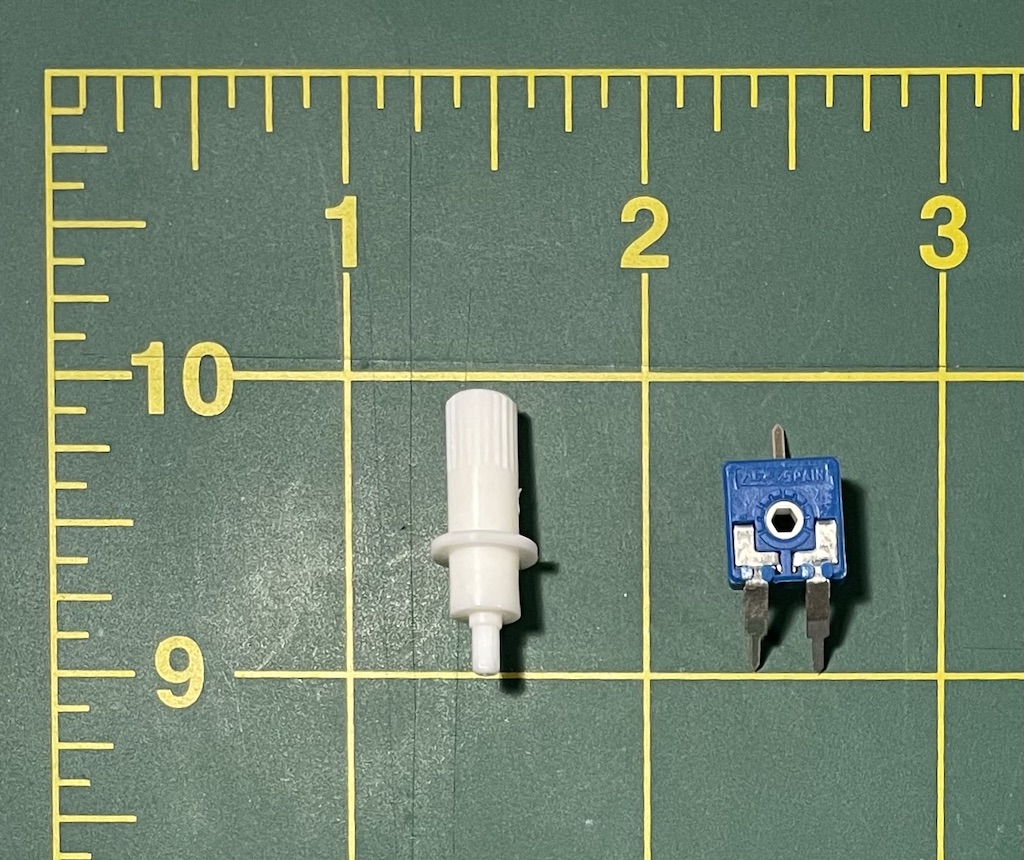
In the Arduino Student Kit, potentiometers arrived in the box looking like Figure 10. Assemble the white peg into the blue box so that it looks like Figure 11. If you have a different kit, you may have a potentiometer that looks like one of the objects in Figure 10.
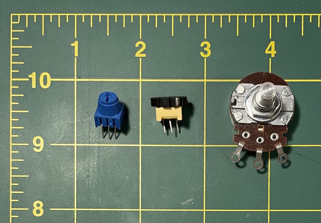
Refer back to the schematic symbol for a potentiometer in Figure 2. As the symbol indicates, a potentiometer behaves like a regular resistor when connected into a circuit using the left and right leads. Each potentiometer has a built-in resistance value that applies across the left-right leads. For the potentiometer in Figures 10 & 11, that resistance is 10 KΩ, or, 10,000 Ohms. Hopefully your potentiometer is labeled. In any case, you can measure the resistance value of with your multimeter by tapping the probes to the left and right leads.
As the schematic symbol also indicates, the middle lead is connected to the twistable knob, and its resistance value changes as you adjust the knob. Let’s try to build the following circuit:
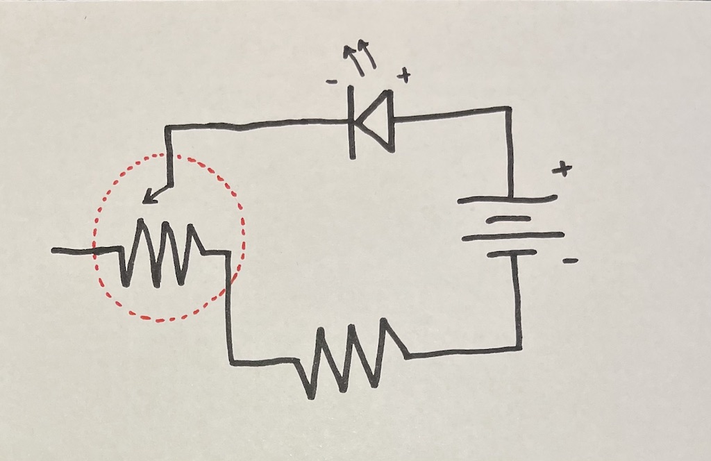
Note that the potentiometer is connected to a regular resister. This is because if you turn the potentiometer knob all the way to the end, your resistance will go down to zero – and we already discussed last week that connecting an LED to a 9V battery with zero resistance will burn it out. Wiring that up, you should end up with something that looks like Figure 14.
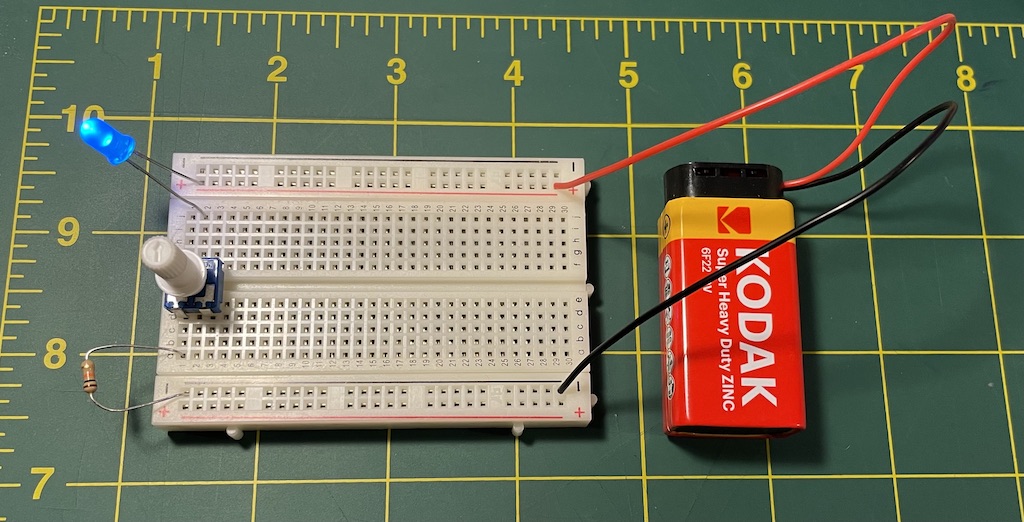
Try twisting the knob to see how the LED brightness changes. Technically, configuring a potentiometer like this in which only two terminals are used is called a rheostat. Next week we will see how to use the third terminal in a configuration known as a voltage divider.
A mini battery
In the last step for today, let’s experiment with a capacitor. A capacitor is an electrical component that can hold a charge. You might be wondering how this is different from a battery. The difference is that a battery, as we discussed last week, is comprised of materials and chemicals (metal and acid) that generates electricity by displacing electrons from one material to another. A capacitor does not generate electricity in this way, but when current flows through it, it is able to store it up for a short amount of time, and then discharge that current again. This works by placing two conductors very near each other, but with something nonconductive in between them, like air or a ceramic layer. We will come back to capacitors again in Unit 2 as a component of much wireless communication.
In the water metaphor of electricity, think of capacitors as like a kind of leaky bucket. As water flows through the pipes, if it encounters a bucket, the water does not initially flow past it, because first it must fill up the bucket. But then once the bucket is filled, it dribbles out water through its leak, and if water stops flowing in, water will continue flowing out for a little while because it will take some time for the water to drain out of the bucket through its leak.
Capacitors can be either polarized or non-polarized. Our Arduino Student Kits came with capacitors of the polarized variety. Polarized means that they are directional elements, like LEDs: they have a positive and negative side and must be connected into a circuit with the correct orientation. We didn’t talk about this before, but the more precise terminology to use with directional elements like LEDs and polarized capacitors is to refer to the positive lead as the anode, and the negative lead as the cathode. As with LEDs, the cathode of a polarized capacitor is usually the shorter lead (wire); and on capacitors, this is usually marked with an arrow, a stripe, or a negative sign.
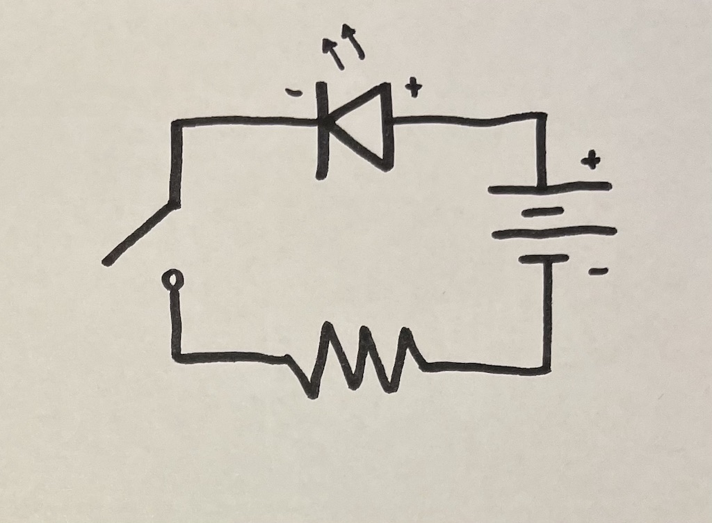
To test out this behavior, let’s build this circuit, taking care to connect your capacitor correctly:
You can use 560Ω resistors here. I recommend assembling a circuit like this by starting at one place and working your way around. For example, you could follow these steps, starting with the battery and going counter-clockwise:
- Connect the battery to the positive and negative power bus, sometimes called a rail.
- To the positive rail, connect a button, but since the buttons are a little hard to connect, put the button across the middle channel of the breadboard and use a wire to connect the positive power rail to the button.
- On the other side of the button, connect a resistor. (This is resister “B” in Figure 15.)
- Now, from the resistor, connect a capacitor to the ground rail.
- Next, from the same pins where you started step 4, connect an LED. Make sure the polarity (positive and negative) of your LED is correct.
- Last, from the LED, connect another resistor (resister “A”) to the ground rail.
You should end up with something that looks like Figure 16.
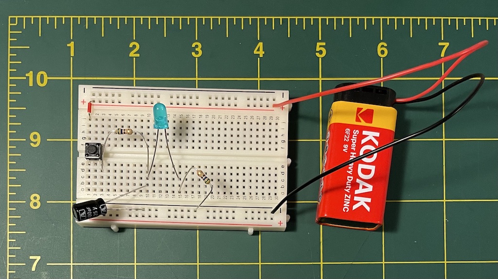
Now, when you press the button, the LED should come on. And when you release the button, the LED should take some time to do a slow fade out.
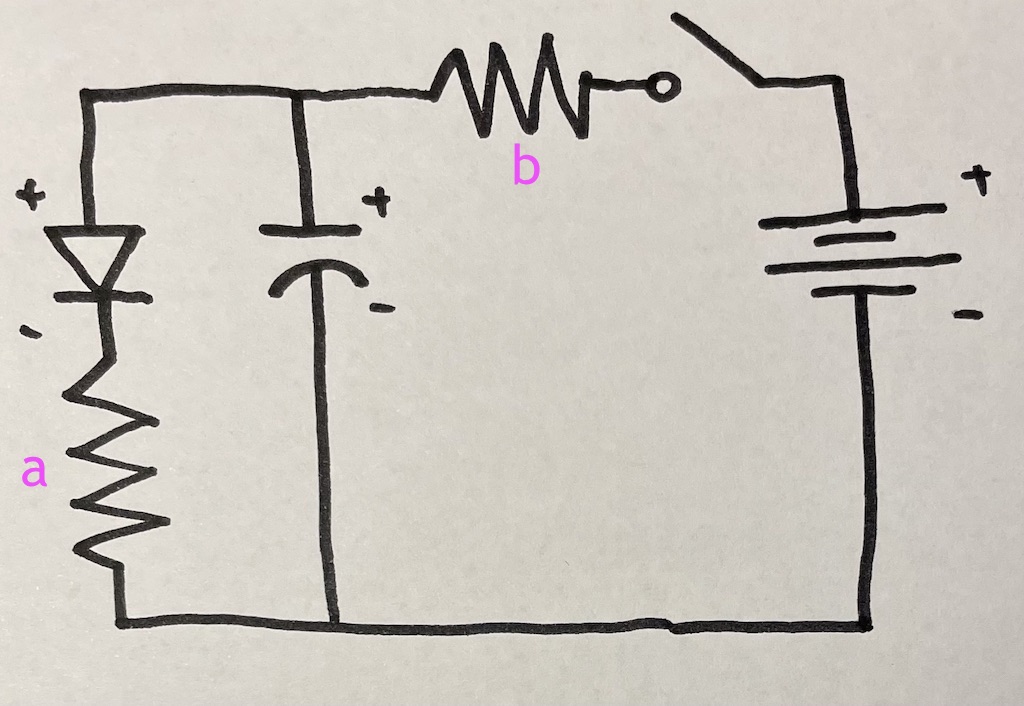
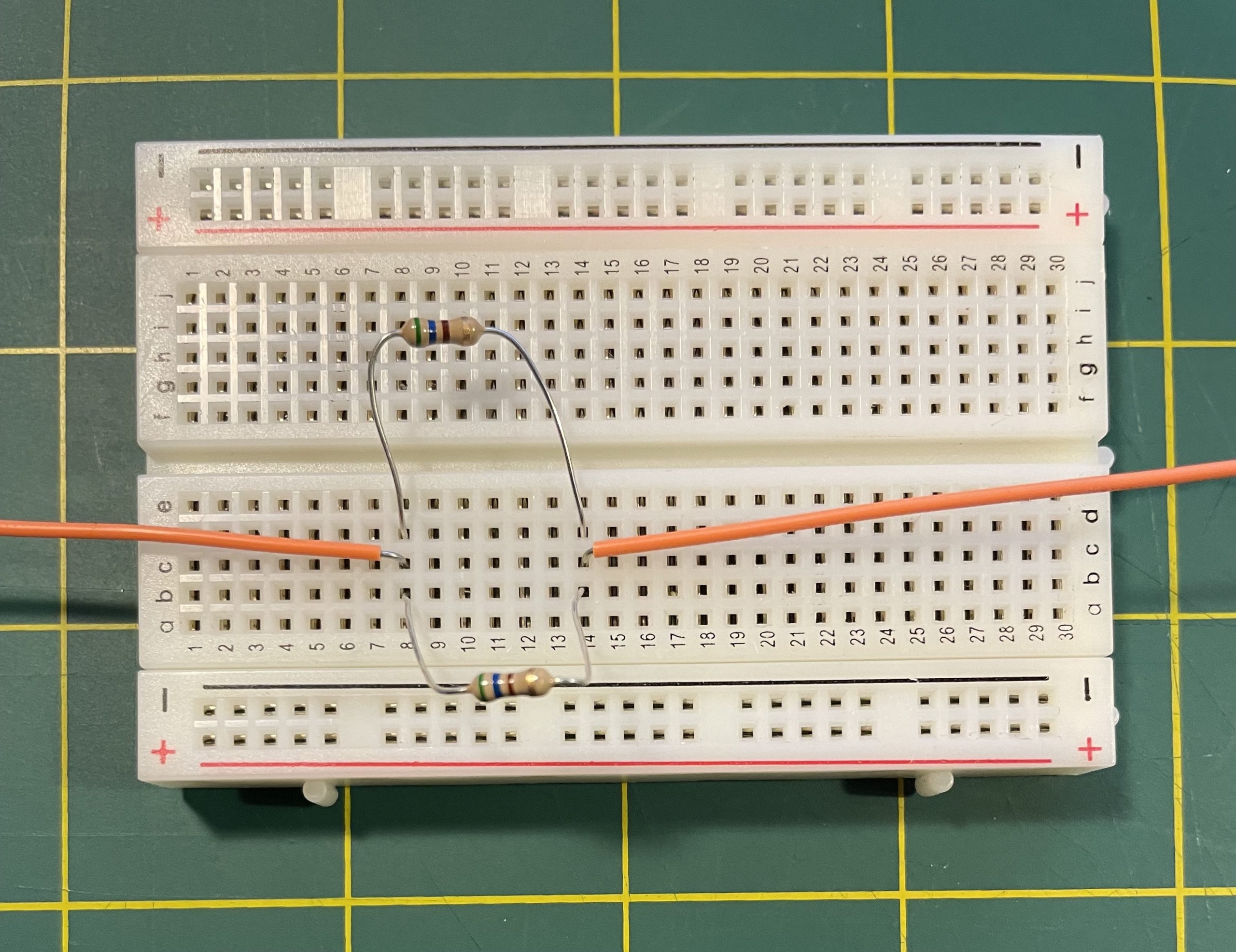
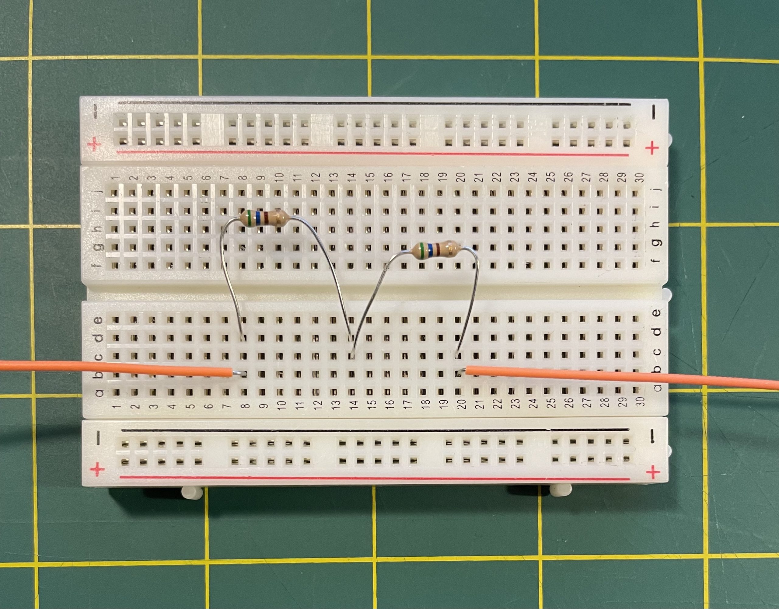
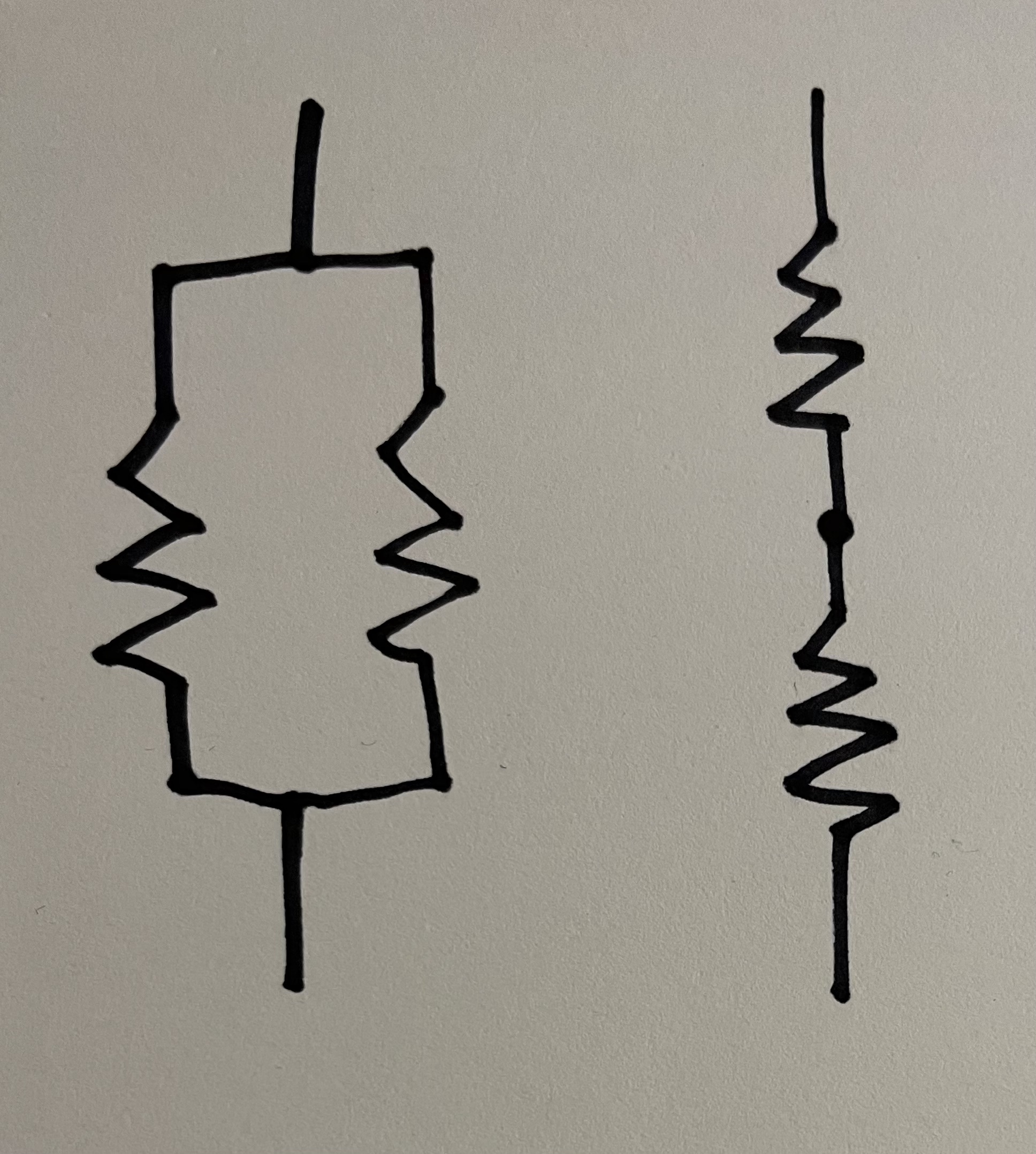
This example introduces a new idea in our circuit-building work and a new schematic pattern. Looking at the diagram in Figure 15, we can describe this circuit by saying that the capacitor is connected in parallel to the battery. If electrical components are connected in parallel, it means that they are connected to the same points within the circuit – in other words, the left leads are touching, and the right leads are touching. This is in opposed to being connected in series, which means that the end of one component is connected to the start of the other. Figure 17 shows two resistors connected parallel, and Figure 18 shows the same two resistors connected in series. (The orange wires in these images do nothing and are only there to indicate that this would be part of a larger circuit.)
When components are connected in parallel, it creates more possible pathways for electrons to flow through the circuit, and more interesting analysis of the circuit and its behavior.
Returning to our capacitor circuit (Figures 15 & 16 above), one way to understand the behavior of this circuit is to say: when the button is pressed, the majority of the current moves around the outer loop of the circuit, through the LED, the resistor, and back to the battery. But when the button is released, the loop containing the battery is broken and the battery is not connected, so current flows around within the smaller loop on the left, from the positive end of the capacitor, through the LED and back – until the charge in the capacitor dissipates.
Hopefully from this you can see how connecting components in parallel creates a kind of redundancy. If one breaks or is disconnected, the others may continue to operate. On the other hand, putting components in series means that if one is disconnected, they all will be. However components in series usually have their values added or multiplied. When resistors are connected in series, for example, their total effect is the sum of all their resistances added up.
To conclude
I hope that these experiments give you some additional insight into the kind of work that we saw by the off-gridders in the book we read and first documentary we watched. They spent quite a bit of time talking about flows and circuits of energy and water – how to direct it, manage it, store it, and dissipate it strategically. Additionally, the skills that you are building up here will give you a technical basis for deeper understanding of many of the digital and electronic tools that off-gridders often use. And finally, there are some interesting conceptual connections beginning to be introduced here: about analog versus digital, and the discrete versus the continuous. These will become more clear in the coming weeks, and especially next week when we start working with Arduino.
In preparation for next week, visit the Arduino website software downloads page, and download and install the Arduino IDE on your laptop. As I mentioned on the project materials page, this tool is free & open source software. It does not cost anything to use and I think you can trust it to install on your machine – it will not install spyware or anything like that. Lastly, make sure that you are able to connect a USB to your laptop – if you need an adaptor to do this, please make sure that you have one. If this is an issue for you for any reason, please don’t hesitate to reach out – I’m happy to try to help you work out a solution.
Homework
As always, create a new lab notebook entry by copying the lab notebook template, naming it with the title & date of this workshop (e.g. “Project, Tutorial 2, Feb 23”), and moving it file into your “Project 1” subfolder.
There are three “lab notebook tasks” described in the class notes above. In addition to those, there is one more piece:
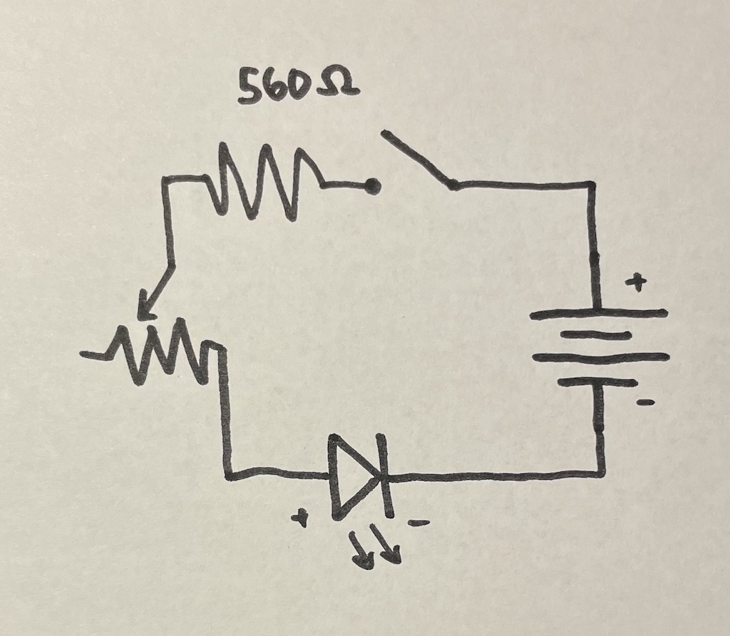
Lab notebook task #4: Try to build the circuit described by the below schematic. Document your effort in your lab notebook. What does it do?
Good luck, and have fun!