Technical Tutorial #4
Recorded video tutorial. Searchable transcript with timestamps.
Review
Last week we looked at different techniques and components that can operate as digital and analog inputs. We saw some techniques for how you might connect these sensors to an Arduino board, including a voltage divider to make sure that any inputs are not floating. We also talked about how Arduino allows you to write computer programs to interact with your circuit, enabling you to modify the behavior of a circuit without changing any wiring or electrical components, by uploading program code to run on the Arduino microcontroller. We ended the lesson last week by uploading the “AnalogInput” program to our boards and using it so that twisting a potentiometer adjusted the blinking speed of the built-in LED. But I did not go into detail about how that code works. Later on today I’ll go into depth about how that program operates.
Please note #1: that I have also added an index of schematic symbols in response to popular demand. You can find this linked from the main menu under “Technical tutorials.”
Please note #2: I have posted the Project 1 assignment. You can find it linked here, as well as in the main menu under “Projects”.
Outputs & actuators
We could sum up last week by saying that we were looking at inputs to your Arduino microcontroller. By contrast, today we’re going to look at some techniques for working with output from your Arduino.
In other words: Last week we looked at how Arduino program code could ask questions about the world with sensors, and today we’re going to look at various techniques for how Arduino can act on the world.
Or to put it in terms of Arduino code syntax: think about how last week we were using pinMode(X,INPUT) and digitalRead(X) (where X is a pin number). By contrast, this week we’ll focus on using pinMode(X,OUTPUT) and digitalWrite(X,VALUE) (where VALUE is a voltage value like HIGH or LOW).
We’ve already experimented with one electrical component that can act as an output from Arduino. Can you think of it? Highlight for the answer: LEDs. Whenever we saw Arduino program code that said digitalWrite() passing a HIGH or LOW value, we were sending an output value from Arduino to the circuit, generating an effect in the world. Today we’ll build on that by looking at ways to generate sound and movement.
Movement
Anything that generates movement from a circuit can be generally referred to as an actuator. There are many components that could be described as actuators. (cf this article from creativemotioncontrol.com.) Often but not always, actuators operate on principles of electromagnetic force. An interesting relationship exists between magnetism and electrical flows. The movement of magnets in particular ways can generate electrical current, and conversely, the flow of current through particular conductors like wire in a coil can generate momentary magnetic fields. This is the principle behind most electrical motors: a coil of conductive material is either placed inside or around a magnet, and as current is flowed through the conductor, it causes a shaft to spin, which is used to drive various other components like a wheel or a gear. Another type of actuator is a solenoid. This operates on a similar principle, but instead of spinning a shaft in coil, the coil induces a linear motion – similar to what the article linked above calls a “linear actuator”. A solenoid could be used for example as an electrically-controlled bolt to lock a door.
Sound
Before we get to motion, let’s start with a different kind of output: a buzzer. The simplest material and technique for making sound with electricity is known as a Piezo buzzer. Piezoelectricity describes a property of certain materials to give off a small electrical charge in response to a physical movement like shaking or jolting. Conversely, when current is applied to a piezoelectric element, it generates small physical movements or vibrations. This kind of symmetry is common among many electrical phenomena. It is the latter behavior that is frequently used as a technique for generating sound: current is applied to a Piezo element, generating small motions which can vibrate to produce a sound. This is also a technique frequently used, for example, in the microphone pickup of an electrical guitar: the plucked strings vibrate at specific frequencies, which in turn vibrate small piezoelectric elements, which generate electricity in a way that corresponds to the musical tonality, which is then passed through other circuitry that amplify the current and convert it back to louder sounds played through speakers.
Piezoelectric buzzers are different from regular speakers though. The typical speaker has a cone-shaped paper wafer that can be made to vibrate at precise frequencies, generating high quality tones, while piezo elements generally produce a more crude vibration, which is why they’re called buzzers, and are not typically used for reproducing sounds like musical instruments or the human voice. But, they are a pretty fascinating material, and we can use them to produce some tones and to experiment with as a technique for generating output from an electrical circuit.
You can actually make a form of piezo crystal known as Rochelle salt at home with baking soda and some other materials. I’ve tried this with some success, following the instructions linked there, but I’ve never gotten my homemade piezo crystals to produce much electricity.
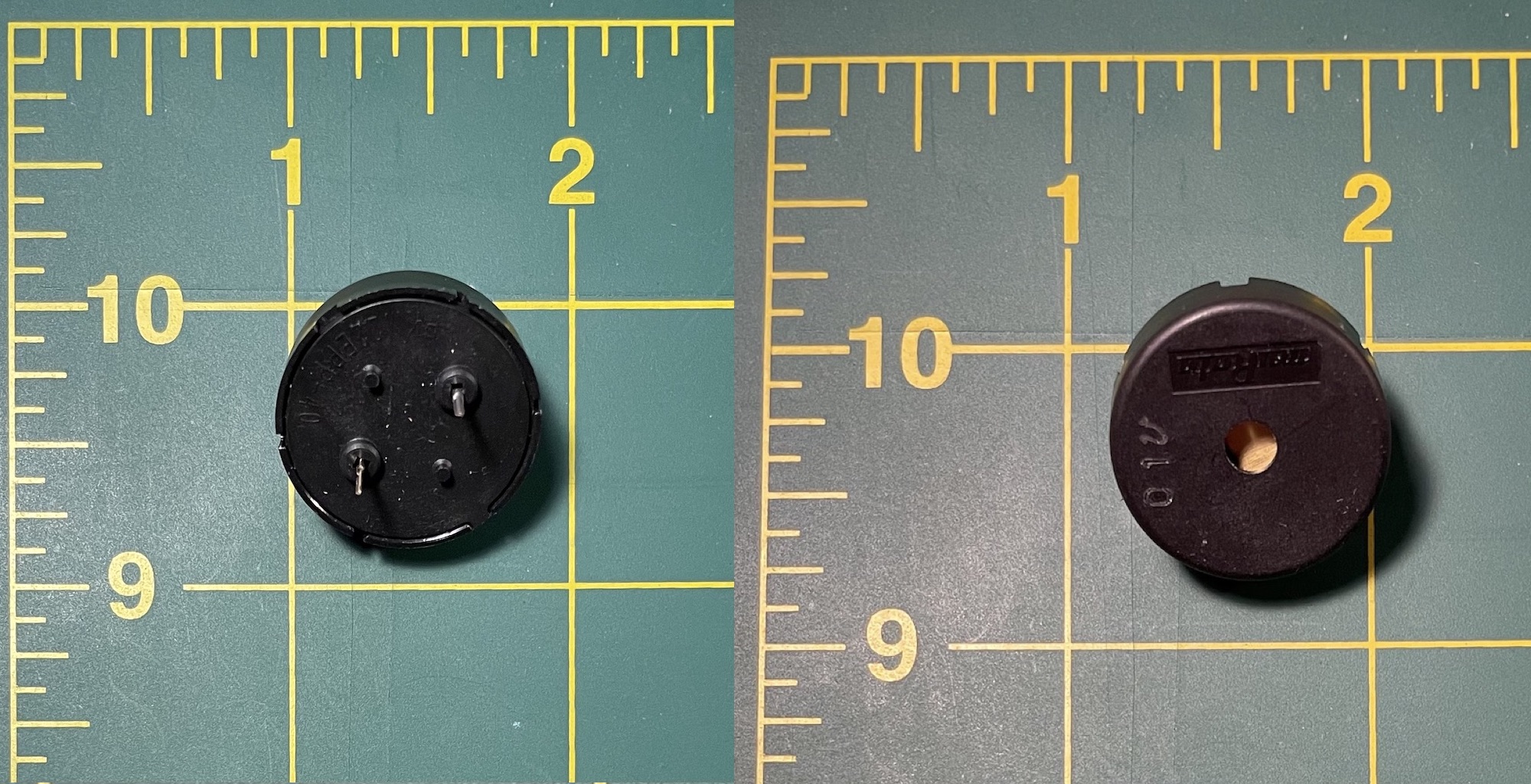
Find the piezo buzzer that came in your kit, pictured in Figure 2.
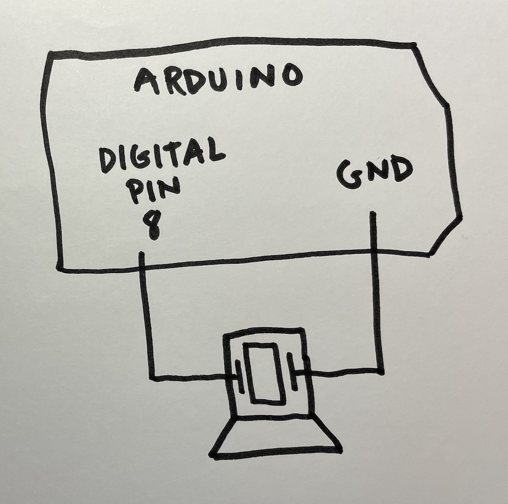
The schematic symbol for a general Piezo element and a Piezo buzzer are shown in Figure 3.

To get started with this, wire up a circuit for the schematic shown in Figure 4.
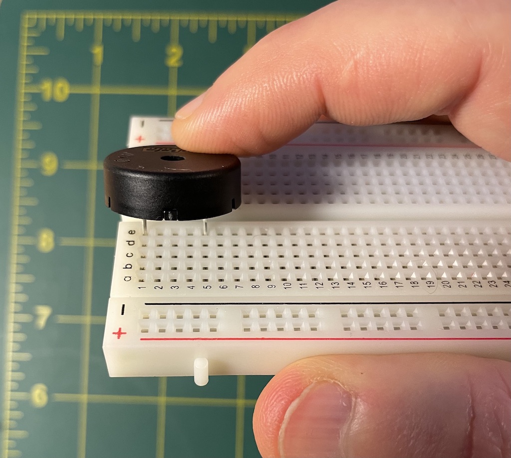
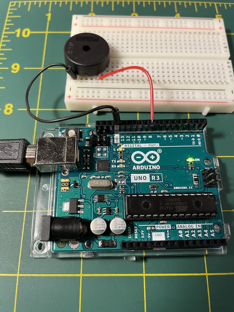
Since the buzzers that came in our kits have an awkward shape that can be somewhat unwieldy on your breadboard, I recommend carefully noting which row numbers you insert it into before pressing it all the way down, then making sure that you use those rows when making connections. In Figure 5 I’m using rows 1 and 5, and then connecting those to GROUND and digital pin 8. After doing that, the circuit for the above schematic should look like the one pictured in Figure 6.
Once we have that built, let’s use Arduino to do something with this circuit.
How does sound work? That may seem like an absurd (or absurdly complicated) question, but before proceeding with this experiment, we have to think for a bit about how tonal sound is generated and perceived. Human hearing works by detecting audible frequencies, which we usually measure in hertz (Hz). Hertz are a measurement of frequency that quantify how many times something happens per second. Hertz can be used to measure anything the repeats periodically, for example: sine waves, computer CPU clock speeds, AC electrical current, or wireless radio signals. In the case of sound, we use Hertz to measure the frequency of small vibrations. Think of this as like beats per minute, just like in a pop song, but much faster. If you tap your desk or snap your finger once per second, we would say this is 1 Hz. As you increase the speed (frequency) of snapping, the Hertz value would increase. At some point, if you were hypothetically able to tap or snap very quickly, human perception would shift from hearing this as separate, discrete clicks, and start hearing them as a vibration. This would happen at around 20 Hz, about the lowest audible frequency. By adjusting this frequency, you can adjust the perceived tone of this vibration. For reference, the middle key on a piano (“middle C”) is 261.6 Hz, and the generally highest frequency sound that can be heard is 20,000 Hz, although this changes with age – a teenager can hear up to 18,000 Hz while an older person won’t be able to hear any frequencies above 12,000 Hz. You can test the frequencies that you’re able to hear with an audio signal like this (via YouTube) – careful to turn your sound down before hitting play and only adjusting it up to safe levels. whew. End detour into acoustics. But if you’re interested in learning more about this, consider taking one of these classes with Lang Professor Clara Latham: LMUS 2053, LMUS 3111. They will go into much more detail about these concepts.
How will we apply this to our Arduino circuit? Well … does this remind you of anything that we’ve worked with already? What about the “Blink” code? The idea here is that we’re going to start with that basic code that we used to time turning an LED on, but now instead use it to time activating a Piezo. Each time we turn the Piezo on, it makes a small vibration which produces a small click. Many clicks per second will generate an audible frequency, and adjusting that frequency will let us adjust that tone.
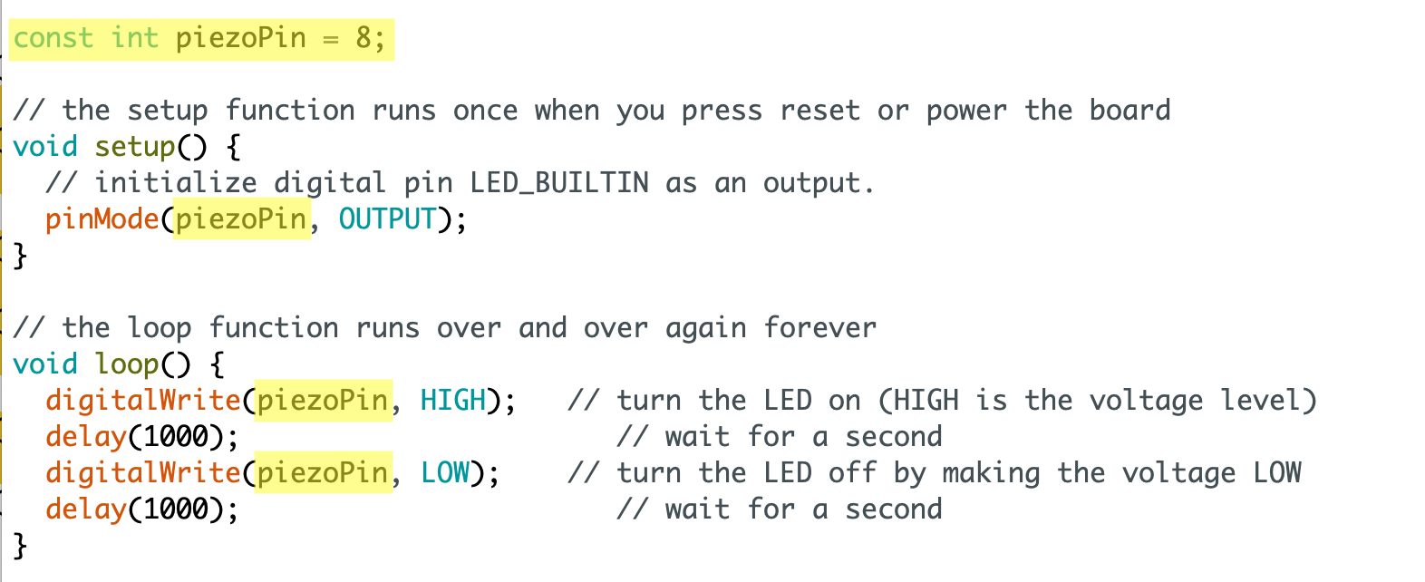
In your Arduino IDE, open File > Examples > Basics > Blink. Modify the code to look like Figure 7 – the modified bits are highlighted in yellow. The changes here create a new variable called piezoPin, which is set to 8, corresponding to the Arduino pin to which we have connected the Piezo. After that addition, the changes here replace all three instances of LED_BUILTIN with piezoPin. As we discussed when we were working with this code to blink an LED, the variable LED_BUILTIN is a placeholder for the number 13, which corresponds to the pin number of the built-in LED for testing.
If you upload that to your Arduino board, you should hear a persistent, slow and steady clicking. Remember how the delay() command controls timing. So this program sets pin 8 to HIGH, waits one second, sets it to LOW, and waits one more second. It repeats this pattern over and over again indefinitely. You could say this is 1 Hz.
Question: Why is it that we set piezoPin to HIGH and delay for 1 whole second, but the Piezo only makes a momentary click – why does the Piezo not play for the whole second? The reason is that when we pass current to/through the Piezo, it only clicks when it’s first activated, almost like it’s jolted. So even though we are sending a HIGH value to that pin for a one full second, we only hear this click which corresponds to the moment when the HIGH signal is first sent.
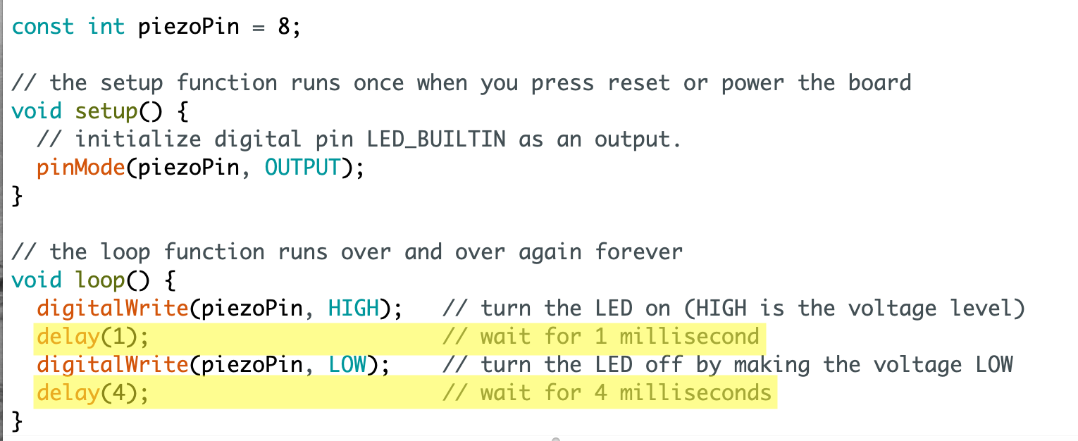
Let’s play an audible tone – let’s say 200 Hz. How could we adjust this code to play a 200 Hz tone? Remember, that means 200 clicks per second. How can we achieve that? Well we’re working with milliseconds here. Remember that 1 second = 1000 milliseconds. And we want to produce 200 clicks per second, so we could play a click every 5 milliseconds, since 1000 ms / 200 = 5 ms. However, we have two delay()s here: one to activate the Piezo (HIGH), and another to turn it off (LOW) so that it can be activated again. So, we could set the delays to 2.5 ms (5 ms divided by 2). Unfortunately the delay() command only takes integers, i.e. whole numbers (this is what the int keyword signifies in the first highlighted line above). So, what we can do is delay 1 ms after setting the Piezo to HIGH, and then delay 4 ms after setting it to LOW. Let’s try that. That will create a cycle of 5 ms total (1 + 4) and achieve the desired goal of 200 Hz. Figure 8 demonstrates how to do this with the code changes from Figure 7 highlighted. Note that I did not need to modify the comments (the text that comes after the //) but I did it just so my note-to-self would remain accurate.
To be honest, this level of precision really doesn’t matter since we’re just trying to generate an audible tone. You could use delay values somewhere between 1 and 5. But I’ve explained this here in the interest of understanding the process. To experiment, try changing the 4 to values like 2, 3, or 5, and re-uploading the code to your Arduino board each time to hear different tones.
For anyone curious, Arduino also has a delayMicroseconds() command (documentation) which accepts microsecond arguments. 1 second = 1,000,000 microseconds. This would give you finer grain control, allowing you to specify shorter delays and thus higher pitched frequencies.
Sound with analog input
What if … What if we want to be able to modify our tones in a dynamic way without re-uploading our code to the Arduino board each time. We could use an analog input with an analog sensor to do this. The objective here will be to use a potentiometer somehow as a control, so that adjusting the knob will adjust the tone being played by the buzzer. To achieve this we’ll use the analogRead() command which we used last week but did not discuss in detail – so consider this somewhat of a review and explanation of how to use this command.
To get started, let’s add a potentiometer to our Piezo circuit, wired up as indicated by the schematic in Figure 9, which could look something like the photo in Figure 10.
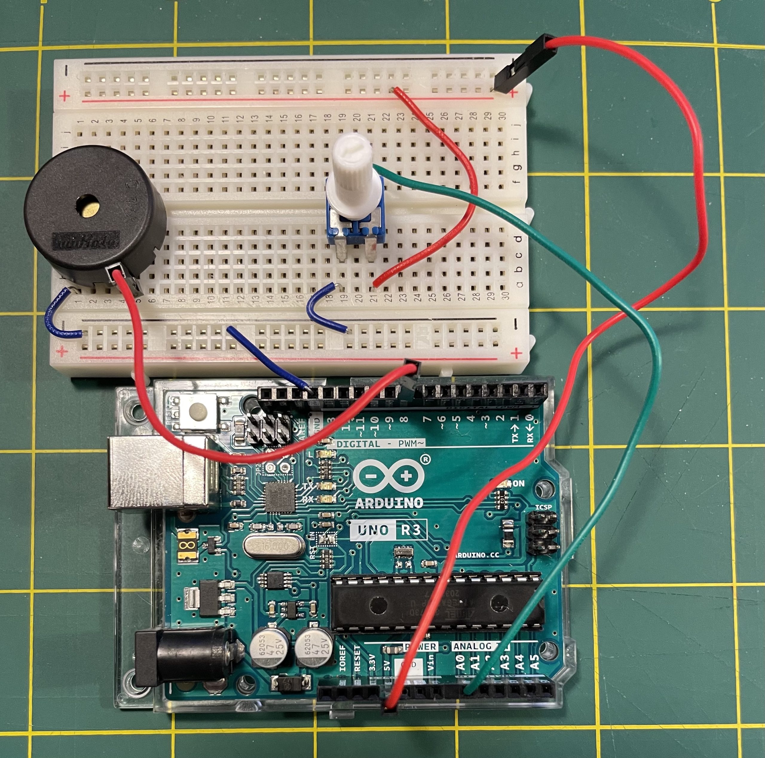
In this circuit I’ve added a positive power bus on the breadboard rail at the top of the image, and a negative power bus to the rail on the bottom. The Piezo is now connected to the negative power bus with the short blue jumper wire, and to digital pin 8 on the other side. For the potentiometer, on the side you can see in the picture, the left pin is connected to the negative power bus and the right pin is connected to the positive power bus, corresponding to the schematic. Then, the middle pin of the potentiometer (view obstructed) is connected to analog pin 0 with the green wire.
The next step will be to modify our Arduino code so the Piezo tone is controlled by the potentiometer. The analogRead() command works by reading (or we might say sensing or detecting) the voltage value being received on one of the “ANALOG IN” pins. The analogRead() command takes one argument, which is a number that corresponds to which “ANALOG IN” pin you wish to read – so, 0, 1, 2, 3, 4, or 5. This command returns a numeric value corresponding to the voltage currently being detected on that pin. It maps this voltage into a numeric range from 0 to 1023, so that a voltage of LOW (or 0V) corresponds to a value of 0 while a voltage of HIGH corresponds to a numeric value of 1023. (By the way, here is the full documentation for this command.) We can then use this number somehow in our program code to affect the behavior of some other part of the circuit. In this particular case, I want to figure out some code so that when analogRead() returns 0, we’ll play a low-pitched tone, and when it returns 1023, we’ll play a higher-pitched tone. And (since this is analog and not digital) as the command returns any value in between, the tone will be adjust proportionally.
Calculating the math to convert Hz to delay() values as we did above can get pretty tricky. Fortunately, Arduino offers a command to make this much easier for us: tone() (documentation). This command take two arguments, a pin number and a Hz value, and it then sets that pin to HIGH and LOW at a timing to produce the desired frequency.
Create a new Arduino program (from the menu select File > New) and type or copy/paste the following code into it:
const int piezoPin = 8;
const int potPin = 0;
void setup() {
  pinMode(piezoPin, OUTPUT);
}
void loop() {
  float potVal = analogRead(potPin);
  tone(piezoPin,potVal);
}
This sets a variable called piezoPin to 8 which corresponds to the digital pin where the Piezo is connected, and sets a variable called potPin to 0 which corresponds to the ANALOG IN pin where the potentiometer is connected. In setup() we tell Arduino that the piezoPin will be used for OUTPUT. Then in the main loop(), we call analogRead(potPin) to get the value on ANALOG IN pin 0, setting that value to a variable called potVal, and then we use potVal in the tone() command to set the Hz of piezoPin, pin 8.
This won’t work quite right though. The range of numbers 0 to 1023 does not work so good as Hz values for audible tones. We need to scale this range of numbers into one that works for us. Fortunately Arduino also offers a command to do this: map() (documentation). Make the following two changes to your program:
const int piezoPin = 8;
const int potPin = 0;
void setup() {
  pinMode(piezoPin, OUTPUT);
}
void loop() {
  float potVal = analogRead(potPin);
  int hz = map(potVal, 0,1023, 40,4000);
  tone(piezoPin,hz);
}
The map() command takes 5 arguments. The first is a variable with a value in some range – in this case, potVal, which can be any value between 0 and 1023. The next two arguments specify what that range of values is. And the final two arguments specify a new min/max range, so that whatever that variable value is will be scaled proportionally into the new range. So in this case I’m mapping from the value range for analogRead() into a value range that will work for a good audible tone: 40 to 4000Hz. The map() command returns that value, which here we’re setting into a variable called hz. Then we’re passing hz in to the tone() command.
Uploading this program to your Arduino board, you should be able to twist the potentiometer to control the tone of the Piezo.
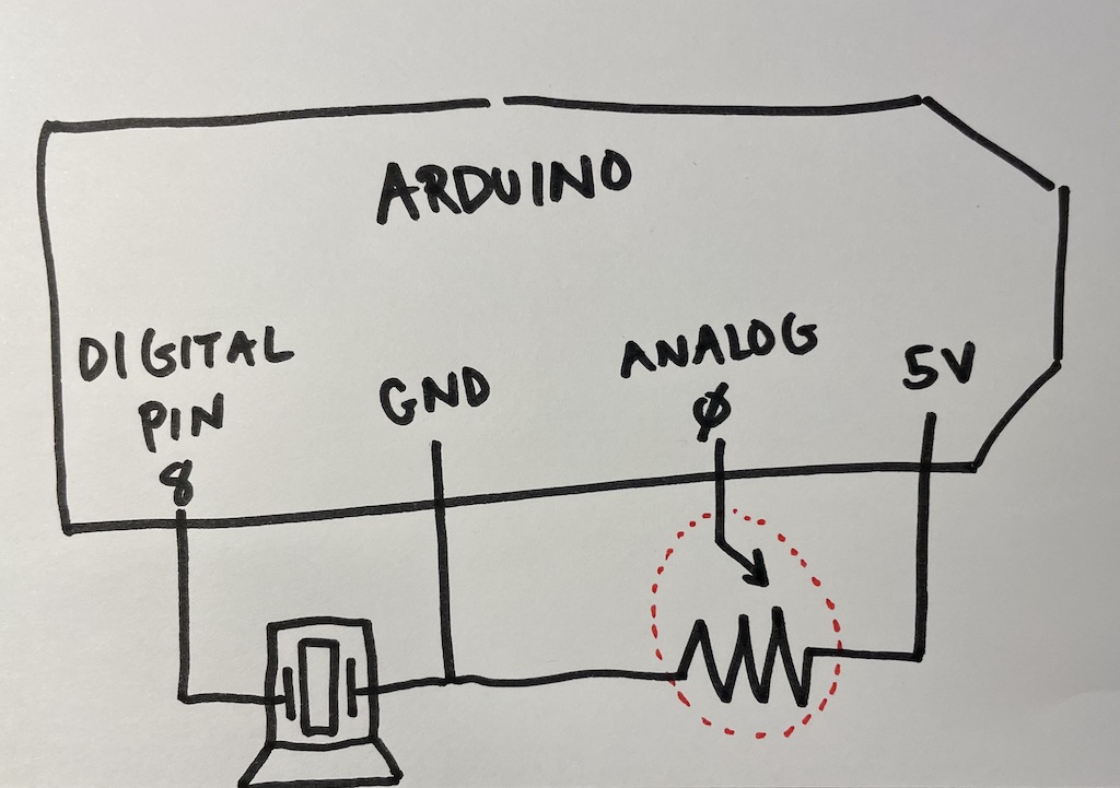
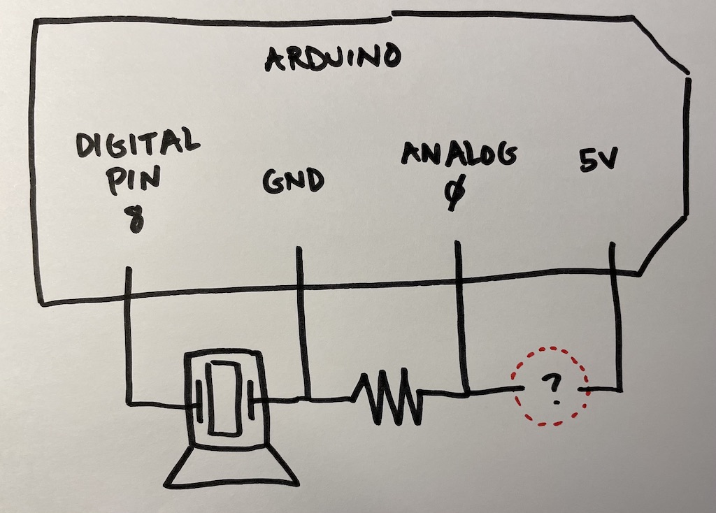
Lab notebook task #1: Look at the schematic in Figure 11. This creates a voltage divider in that the sensor indicated by the red circle goes from 5V to analog input 0, and also connects to a pull-down resistor that goes to GROUND. Wire up this circuit. You can use Figure 10 as a starting point, or start from scratch. For the red circle component, you can use your phototransistor (the thing that looks like a clear LED with a flattop). You should be able to use the same code as above. If you can get that wired correctly, then adjusting the light shining onto the phototransistor should alter the tone of the Piezo in a fun way. Document this and add some notes about the process to your lab notebook.
Movement
Finally, let’s experiment with generating some movement and motion as a form of output. We’ll do this with a small DC motor that came in your Arduino Student Kit. A motor is an electronic component that generates some kind of motion when activated with an electric current. There many different types of electric motors, the two main types being servo motors and stepper motors. Wikipedia has a good discussion of the differences. Our Arduino Student Kit came with a servo motor so that is what we’ll be using.
The servo motor in your kit should be easy to find and is pictured in Figure 12. Notice that it has a plastic white connector without any pins. To connect this into a circuit, you will need to affix wires into the three pin holes of the connector. I like to try using red and black to correspond to the red and black wires of the motor. These correspond to the negative (black) and positive (red) connections of the motor. I suggest you do the same. I also like to use a white wire for the middle pin if possible, but any color will do.
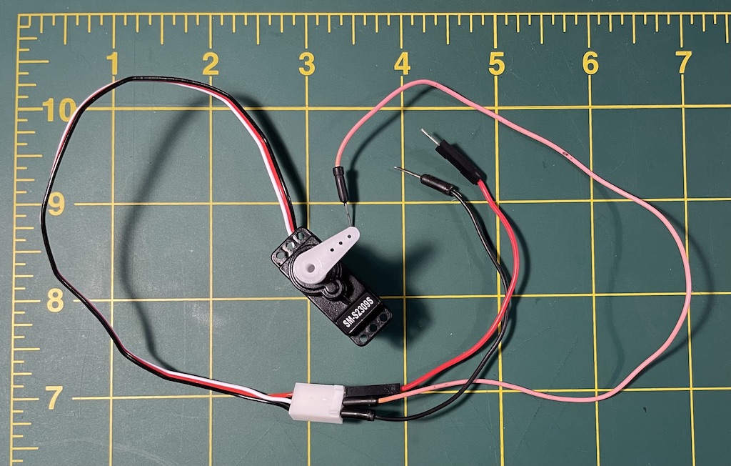
The servo motor has a small white plastic shaft which is the thing that will rotate. It comes with several different attachments which you can choose from depending on the application you are working on. I’ve attached the single arm pictured in Figure 12. When you’re working with a servo on a project, you may want to screw this part in for greater stability, but for now, leaving it like this will probably make it easier to swap it out later.
To get started, let’s wire up this circuit pictured in Figure 13. Don’t be intimidated by this schematic. It’s really quite simple. See Figure 14 for a photo of a circuit that implements it.
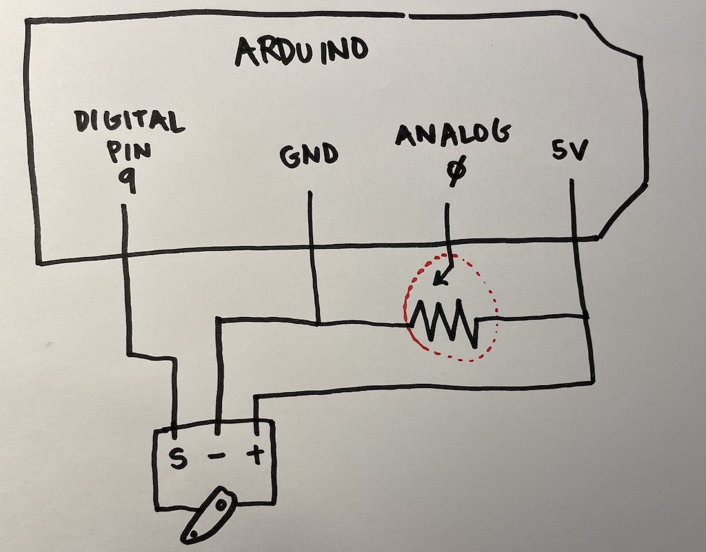
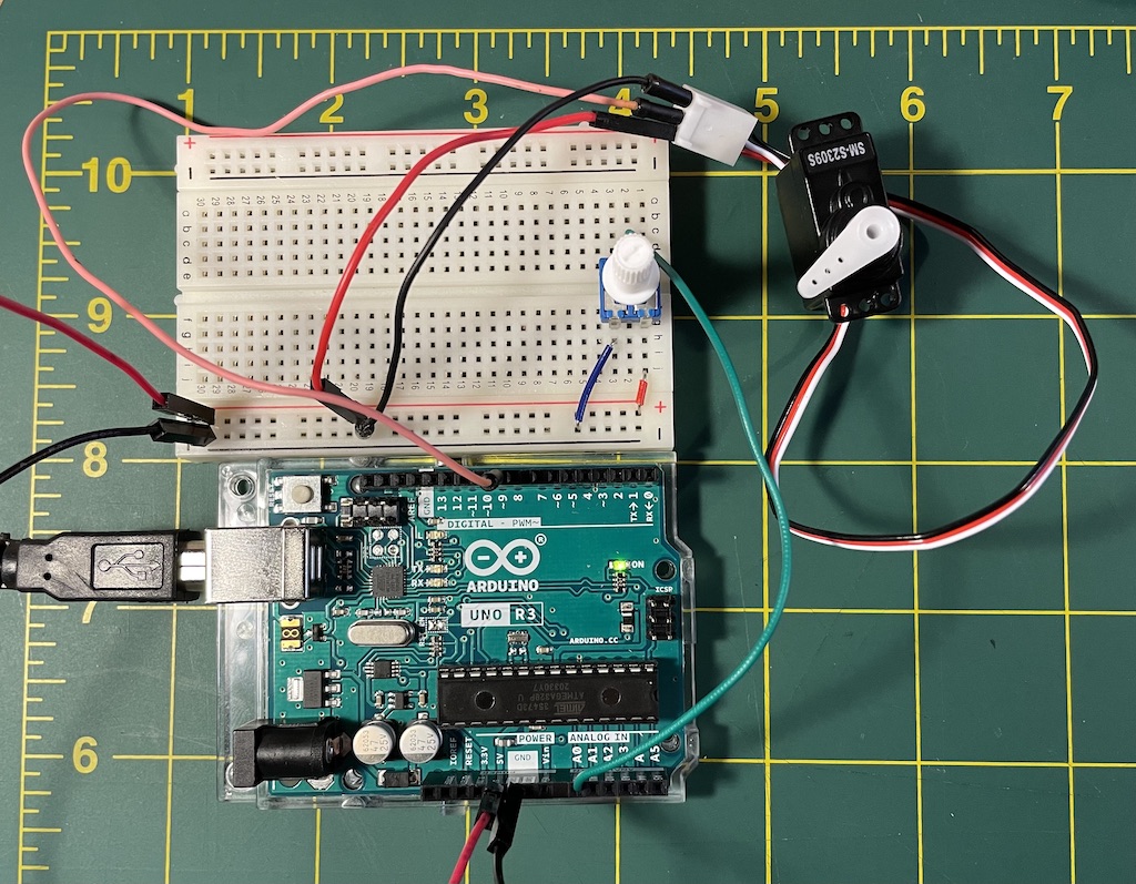
Walking through that, notice that I have connected both positive and negative power buses to the breadboard rails at the bottom of the picture. (The black wire that extends off-frame to the left is the one connected to GROUND on the Arduino at the bottom of the photo, and similarly, the red wire that extends off to the left connects to 5V on the Arduino.) The servo and the potentiometer are almost separately wired in a way. The potentiometer has one pin going to the negative power bus (the blue jumper wire), one to the positive (the red jumper wire), and the middle pin (green wire, view obstructed) connected to analog pin 0. The servo is similarly wired up to the positive and negative power bus, with the middle pin connecting to digital pin 9. This is the pin that will be used to control the motor.
To make this work is very straightforward. Open up File > Examples > Servo > Knob. If you’ve wired up your circuit as above, you shouldn’t need to modify this example code at all. Simply upload it to your board, twist the potentiometer, and see what happens.
(A tip on working with your Servo from adafruit.com: “If the Servo Misbehaves”.)
Lab notebook task #2: Can you work with this circuit as you did in task #1 today? In other words, replace the potentiometer with a different analog sensor (perhaps the phototransistor) and see what happens? Remember your pull-down resistor!
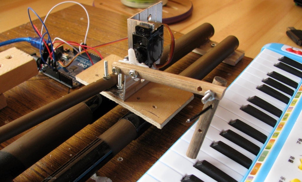
Lab notebook task #3: Building on task #2, think about some non-circuit crafting you can do to make your servo motor into a kind of meter. Affix it to a piece of paper or board so that as you adjust your phototransistor (or other analog sensor), the servo moves a pointer indicating levels of brightness (or whatever your sensor is detecting).
Powering your Arduino “off-the-grid”
Since I think some of you will be thinking about disconnecting your Arduino from USB (“from the grid”) for the project and powering it via batteries instead, here are a few blog posts that I found helpful in thinking about this:
- An article about how to do this
- A cautionary blog post about why the above isn’t a great idea: “9V Batteries suck and why you shouldn’t use them”
- And another harsh reality check: “Arduino misconceptions 6: a 9V battery is a good power source”
- But some reason for hope for the possibility of a workable solution
In the end, there is not a great way to power your Arduino without being connected to USB. I’m looking into it. When we start working on projects, feel free to run them off USB, and we can all keep in mind that Arduino could be used in an off-grid context if we wanted to buy some more powerful batteries, or work out solar solutions. The project can still be a good learning experience if it forces us to think about these questions, even if we don’t have a neat and tidy solution to all of them.