Technical Tutorial #3
Recorded video tutorial. Please note that I tried to constrain this to one hour, but it ended up at 1 hour, 20 minutes. Also, I tried a new recording technique for this one which I hoped might improve the video quality, but I don’t think it helped much and inadvertently it did not generate an audio transcript. Apologies for any inconvenience.
Reading: Additional selections from The New Way Things Work, by David Macaulay: several sections about different sensors, and pages 340-341 about transistors. I’ve included these additional sections from this book that will help you think about how electronic and digital sensors work. Page 294 talks about a breath test; page 295 a smoke detector; and page 302 explains a metal detector. Pages 315-17 explain binary on/off button inputs like in a keypad or keyboard; pages 318-19 explain the computer mouse as analog sensors in two directions (up/down, left/right); and page 321 explains digital thermometers and electronic scales. I also hope some of the discussion here might give you inspiration for your project.
Review
Last week we talked about different electronic components that can modify how current flows through a circuit: buttons, potentiometers, and capacitors. For the last part of your homework you were asked to build a circuit that combined a potentiometer and a button so that you could adjust the brightness of an LED and turn that LED on/off at that brightness. So like a dimmer control for a lamp with an on/off switch.
A more complicated button configuration
Last week we also saw how you can build a simple circuit with a button such that it turns an LED on only when the button is pressed. But what if … (Leading question that brings us to a key point for today.) What if you wanted to modify this circuit so that when the button is pressed, the LED is off, and when the button is released, the LED is on? Can you begin to think how you might try to implement such behavior? Is this possible to do given what you know now?
In the example from last week (when pressed button meant LED on), the button acts as a simple valve: when the button is pressed, it’s like it’s letting water flow, and the water is powering a component. In the new example (when pressed means off) the button can no longer simply give the LED power directly. But now in response to my question, the button has to somehow indirectly control some part of the circuit. The button has to logically control the flow of current. This is often called a gate. There are several methods to achieve this. We’ll talk about two.
I. The first method would involve the use of a transistor. (We’ll discuss this, but not implement it.) Transistors are made of semiconductors. Remember our friend the LED: a light-emitting diode, where a diode is a component made of a semiconductor that allows current to flow in one direction but not the other. Transistors are made of semiconductors whose conductivity from one point to another is influenced by the presence of electrical current in between. There are many different types of transistors. In order to build a circuit that implements the behavior described by my question above, we could use a PNP transistor, illustrated in Figure 1. In a PNP transistor, when electricity is flowing to the gate, it blocks current flowing from input (source) to output (drain). (Other types of transistors called NPN work in the opposite way: they only allow current to flow from input to output when current is flowing to the gate. Pages 340-341 of the Macaulay text, linked above, include an illustration of an NPN transistor as well as the PNP transistor illustration in Figure 1.) Hopefully you can think how you would build a circuit using a PNP transistor so that when a button is pressed, it sends current to the transistor gate, cutting off current to an LED, while releasing the button would let current flow to the LED.
II. A second method to build a circuit that implements the behavior posed by my question above involves using your Arduino. And before we can get to this, we have to take a detour to introduce and learn about this device …
Introducing Arduino
Arduino is an open-source hardware and software platform.
Arduino is at the center of a large community of enthusiasts, as well as a company. You might be familiar with what it means for software to be open source: that the human-readable source code of a computer application is freely available for anyone to copy or modify, as long as whatever they make with it is also open source. Applying the open source ethos to hardware is a bit trickier since it’s not possible to freely copy hardware. What open source usually means in terms of hardware is that all the plans and specifications for the hardware are freely available, meaning that anyone with the skills and tools to fabricate a circuit should be able to build their own identical replicas. Arduino the company sells Arduino boards, but other companies also have boards manufactured in other factories using the open source Arduino blueprints, such as Elegoo, which you may have seen for sale on Amazon. (Wikipedia has a list of other projects manufacturing Arduino boards.)
Side note: Thinking about open source hardware and the off-grid ethos. Theoretically, with the Arduino open source blueprints in hand, we could manufacture our own Arduino-compatible board if we had the expertise, access to the requisite machinery, and a supply of the various components that comprise the board – taking a DIY approach to the infrastructure of this DIY circuit work. It’s interesting to think about this manufacturing mode in the context of the off-the-grid ethos. If one were aspiring to total off-grid living, could open source hardware manufacturing accommodate that? Perhaps. See all the lighter green lines etched into the bottom of the circuit board (the entire green part of the Arduino)? These are the conductive pieces of the circuit of the Arduino board itself. This is called a PCB (printed circuit board). One could acquire a PCB printer (for example [1], [2]) to create the board. But all the required components would still be needed. This opens up all the supply chain & dependency issues that we started thinking about with Vannini & Taggart. Pragmatically there is simply too much complexity and expertise required for a person to be wholly autonomous when working with this kind of technology. Does that mean that digital machinery then is somehow necessarily social machinery? Tying us to others even as we often feel it to be isolating. An open question …
If you’ve ever seen or heard of Raspberry Pi, you might be wondering how that relates to Arduino. They are very similar. Both projects share a similar ethos. While Raspberry Pi is not open source, we might say it has a kind of open source spirit, and there are a number of open source projects that intend to mimic Raspberry Pi. The main difference is that Raspberry Pi is powerful enough to be a small computer like your laptop. It can connect to a keyboard, mouse, and monitor, and it can run an operating system like Linux or Windows (or Mac, but this is less common and more challenging). On the other hand, Arduino is much less powerful. It cannot be connected to a monitor or keyboard. It is primarily designed to run very simple computer programs that integrate with simple circuits like the ones we’ve already been building.
Getting started
If you don’t already have the Arduino software downloaded and installed on your computer, you’ll need to do that. Unzip the downloaded file and move it into the place where you install software (“Applications” folder on Mac, “Program Files” on Windows). Open up this application. You should see a green and white window as in Figure 3.
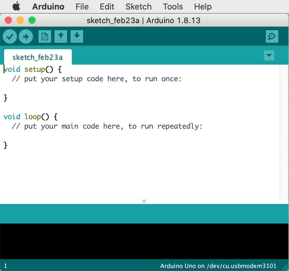
This is the Arduino IDE. IDE stands for “integrated development environment.” That means that it is an application that you can use to write computer programs (i.e. software “development”) that is also “integrated” with the other tools that you need to compile, run, and debug those programs. (If you have ever worked with Processing, this workspace should look familiar. Arduino was designed following the Processing project, so it has similar underlying concepts and patterns of use.)
As you probably know, a computer program is comprised of lines of text, in sequential order, listing specific instructions that humans can read and that tell a computer how to operate. Computer programs are written in programming languages which define all the instructions that you are able to use to operate that particular machine. Arduino uses the Arduino programming language. If you have ever done any programming before in Javascript, Python, Java, Processing, or something similar, a lot of syntax in Arduino will look familiar, but there are many differences as well. To be precise, Arduino is actually based on the C programming language. If you have never done any programming before, that’s OK! We’ll walk step-by-step through any coding that you’ll need to do for this class.
For the next few weeks we’ll experiment with working on Arduino computer programs to control circuits like the ones we’ve been building. The Arduino programming language includes many shortcuts and instructions for interacting with circuits. Using a platform like Arduino allows you to write code to operate a circuit, and to make changes to the circuit’s functionality by changing program code, instead of only being able to modify a circuit by making changes to its wiring and layout. In other words, so far you have been working with hardware components, and now you will also be building software components (computer programs) to interact with them.
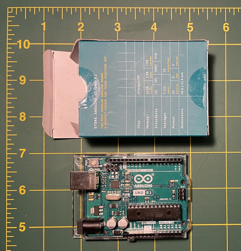
Arduino code is typed in the large white box of the IDE window. Then that code is transferred onto the central chip of your Arduino board through a process called uploading. The main chip of the Arduino is called a microcontroller: a CPU like the kind in your computer, but smaller, simpler, slower, and less powerful. This is the largest component on the board, the thing that looks like a piece of a Kit Kat bar. The Arduino uses a microcontroller called an ATmega (more info in this article) – other CPU brands you may have heard of are Intel (Core i5, Pentium, Celeron), AMD, Nvidia, arm, Motorola, etc. Modifying the code running on this chip allows you to change the behavior of the various pins of the circuit board, in terms of timing, turning components on and off, and reading voltage values.
After you upload an Arduino program to your microcontroller, it stays there forever and runs continuously until you erase it or upload something else. You do not need to re-upload the code every time you want to run it. But if you ever need to restart the program running on your board, you can press the “RESET” button which is the small, round, white button next to the USB plug.
Let’s upload & run our first Arduino program:
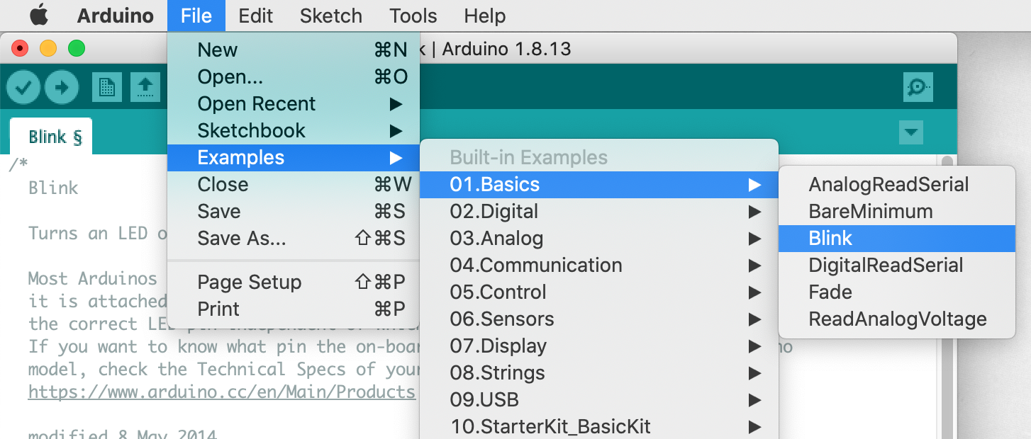
(1) Start by opening up a basic program called “Blink”.
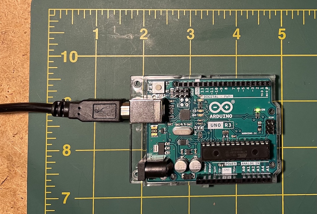
(2) Connect your Arduino board to your computer with the USB cable that came in your kit.
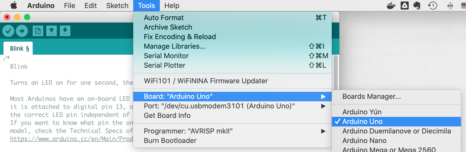
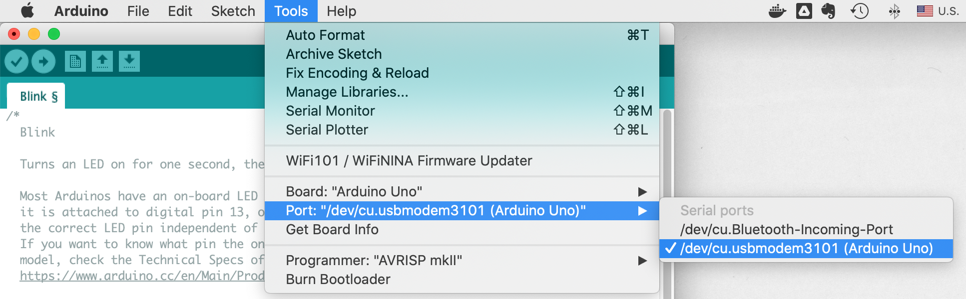
(3) (Important step that people often forget!) From the Tools menu, make sure you select the correct Board and Port. For Port, any USB device should work fine. Hopefully you see one that says “Arduino”. See Figures 6 & 7 and their captions for more detail.
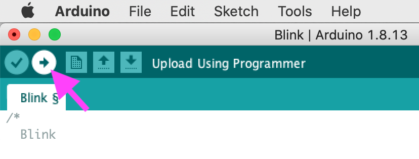
(4) Finally, click the “Upload” button as indicated in Figure 8 to upload this program to your board. When you do this, you should see the “TX” and “RX” lights on your board flash, and then you should see the “L” light blinking.
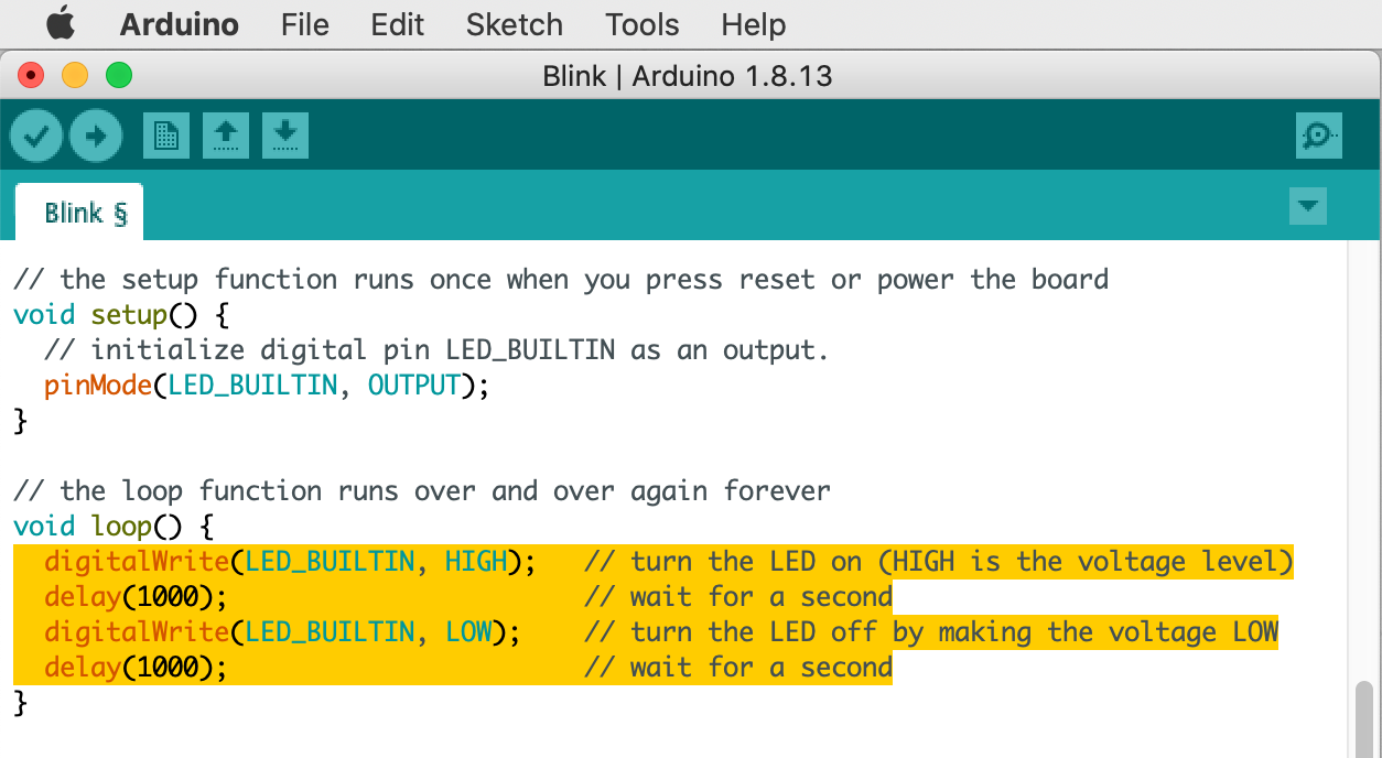
Find the four lines of code highlighted in Figure 9. Without even knowing any commands of the Arduino programming language, you can probably start to intuit what these commands are doing. They are doing a digitalWrite() to the built-in LED pin, setting it to HIGH – or in other words to 5V, turning the LED on. Then calling delay() which will wait some amount of time. This number is in milliseconds, so 1000 equals one second. Then the program does a digitalWrite() to LOW setting the pin to 0V to turn the LED off, and waits another second. This algorithm is what creates the blinking behavior.
Can you start to think about how you might modify this to change the behavior? What about if you wanted to make this blink in a Morse code pattern? Start to copy-paste some of these lines to experiment. Here is a Morse code program that blinks the pattern for “S-O-S”.
Lab notebook task #1: Look up the Morse code characters for your name (or any sequence of a few letters that you wish). Create a new Arduino program (from the menu click File > New) and copy/paste all of the Blink program code. Modify it to blink your Morse code characters. Upload it to your board. Observe the results. Save your file and name it “tutorial3-morse”. Then from the menu click Sketch > Show Sketch Folder. Locate tutorial3-morse.ino and drag this into your “Project 1” folder in Google Drive.
A tour of your Arduino
Have a look at the Arduino board. Note the “TX” and “RX” LEDs. These indicate whether your Arduino board is transmitting or receiving data. They will flicker quickly every time you upload a new program to your board.
Lab notebook task #2: When you are uploading a program from your laptop to your board, naturally you might think that the “RX” light on the board would flash to indicate that it is receiving data. But the “TX” light also flashes indicating that it is also transmitting data. Why might this be? Speculate about why and add these comments to your notebook.
There is a built-in LED for testing labeled “L.” You should also see a power indicator LED labeled “ON”. The board also has a USB jack, which you’re already using, and a barrel connector for a battery, which we’ll use later. It also has 14 pins for digital inputs and outputs (0-13), and 6 pins for analog input (A0-A5). There are two locations for ground, labeled “GND”: on the digital side and the analog side – these are identical and can be used interchangeably. Finally, you have two power pins: 5V and 3.3V. You can build circuits exactly as we’ve been doing so far by using your Arduino in place of the battery: connect the GND pin as the negative terminal of your battery, and the 5V pin as the positive.
Getting back to the button question …
We’re getting closer to working out a solution to my question about how to implement a button that is pressed for off and released for on.
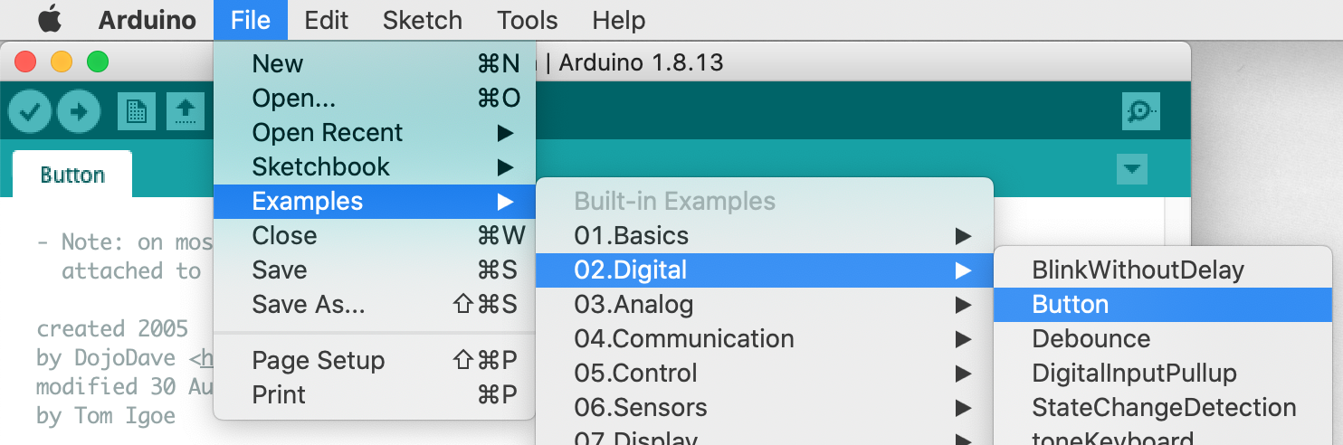
Open the Arduino program called “Button” as shown in Figure 10.
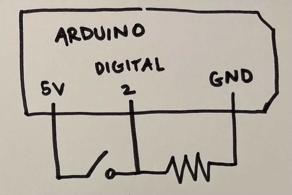
In order to run this program, we’ll first need to build the basic circuit illustrated in Figure 11.
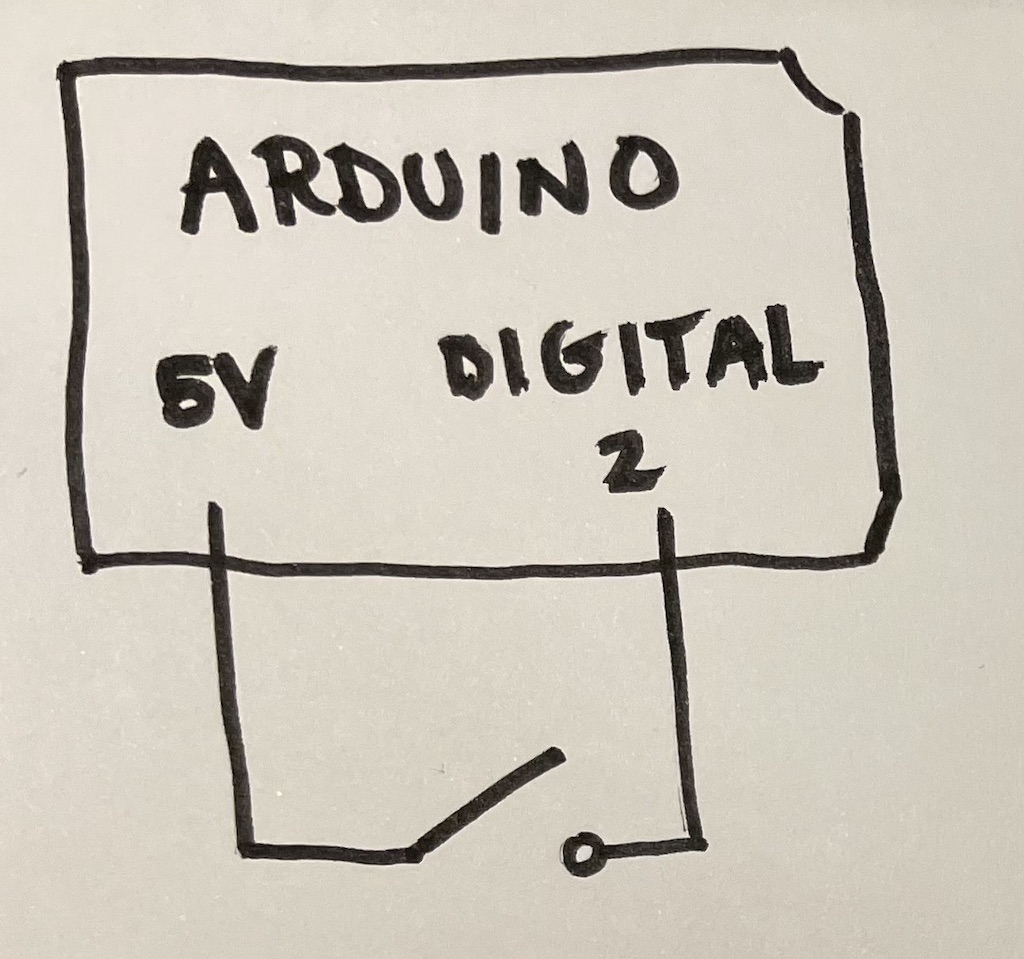
There is no standardized schematic symbol for the Arduino board, so I will render it as a box like this, and I will draw labeled lines coming out of the box to indicate which pins we are currently using.
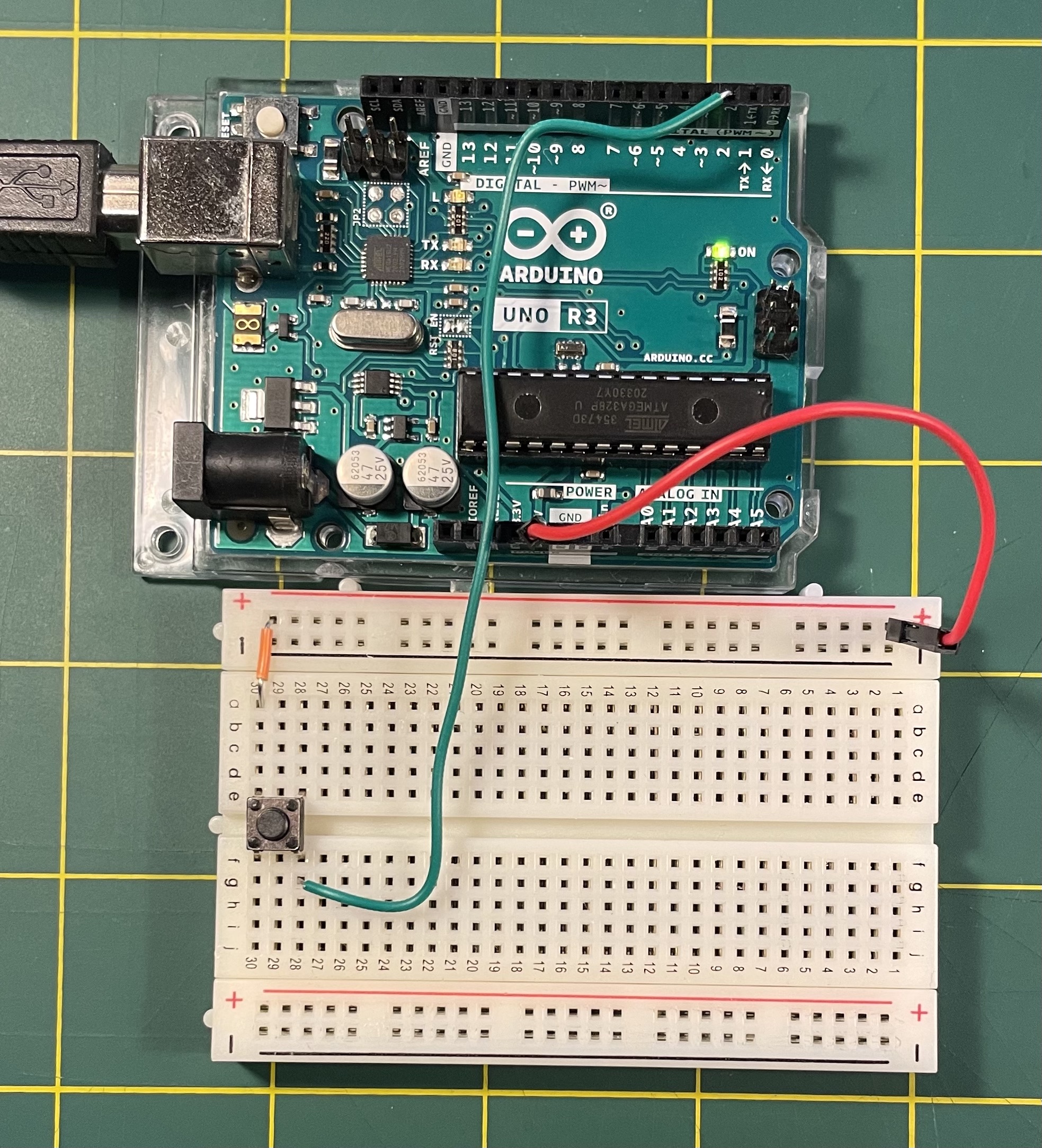
Implementing that schematic as a circuit should look something like Figure 12. Note that the red wire is connected to the pin labeled 5V and the green wire is connected to the pin labeled 2 on the digital side.
Upload the “Button” program to your board. The goal here at the moment is that pressing the button should turn the built-in “L” LED on, and releasing the button should turn it off. But, what you probably will actually see is some strange behavior! Releasing the button, the light will probably only slightly dim or flicker. Let’s figure out what’s going on.
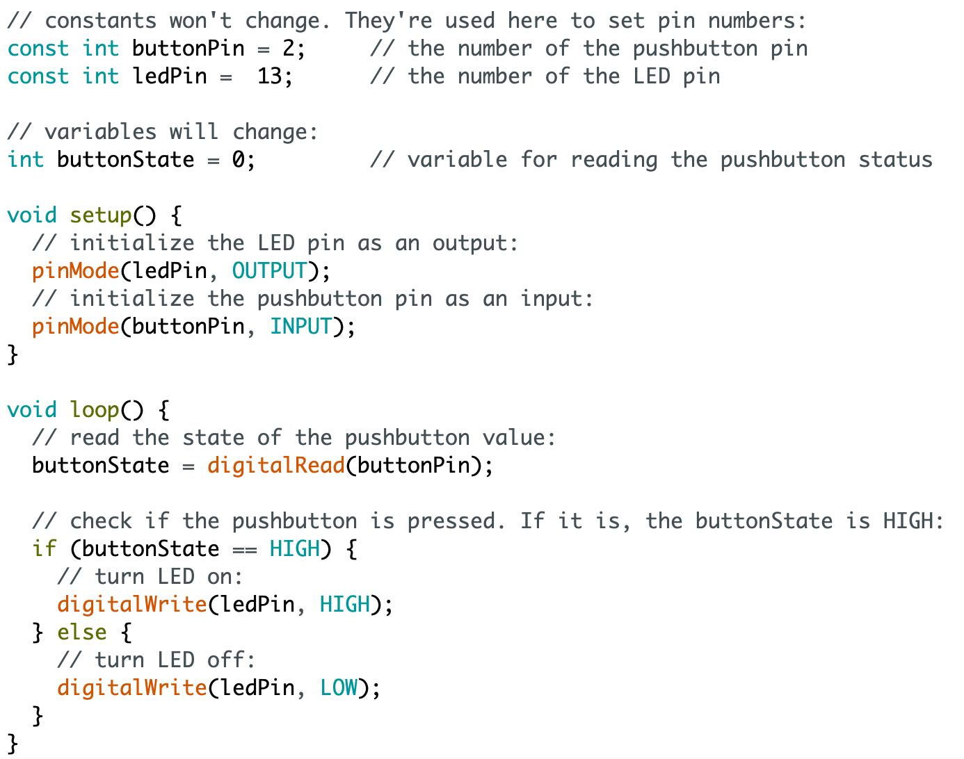
First let’s look at the code currently in your IDE, or above in Figure 13. First we set some variable values that we’ll use throughout: buttonPin is a variable with the value 2, which we’ll use as a placeholder throughout this code to refer to pin number 2 on the digital side, and ledPin is a variable with the value 13, which we’ll use to refer to the digital pin number that is linked to the “L” LED. buttonState is a variable that will hold the state of the button: 0 will mean not pressed, and HIGH will mean pressed. All the code in the setup() block runs once when our board boots, i.e. starts running. In this block, we establish that ledPin (pin 13) will be used as OUTPUT: we will set it to HIGH or LOW (0) to turn the LED on or off. On the other hand, buttonPin (pin 2) will be used as INPUT, we will use this pin to read a value from our breadboard circuit. The code in loop() runs over and over again and this is what will control our circuit. In this case, we use it to do a digitalRead() on the buttonPin (pin 2). This asks: what is the value of pin 2? Is it HIGH (5V) or LOW (0V, GROUND)? The rest of the code says if the buttonState is HIGH, then digitalWrite() HIGH to the ledPin (pin 13) to turn the LED on, otherwise (else) digitalWrite() LOW to turn the LED off. Hopefully that seems simple enough.
Next let’s analyze the schematic in Figure 11. When the button is pressed (when the switch is closed) you can see that digital pin 2 will be connected to 5V. But when the button is released (when the switch is open), what do you think digital pin 2 is connected to? The answer is that when the switch is open the digital input is connected to nothing, it is an open circuit. This is called floating, and it is the cause of the strange, erratic, unpredictable behavior that we’re seeing because the Arduino code is trying to read a HIGH or LOW voltage value on digital pin 2 but it is seeing a floating value.
We can fix this by creating the schematic in Figure 14, which is called a voltage divider. This adds a resistor from digital pin 2 to GROUND: a technique called a pull-down resistor. This means that when the button is released, digital 2 pin will reliably read a GROUND value. There is some room for experimentation in the value of the resistor. I recommend trying with 10,000Ω, but you can also experiment with a smaller value in the 500-2000Ω range. (If you’d like to read more about how to determine a good resistance value for a pull-down resistor, I can recommend the discussion here, or some simpler discussion in this tutorial on the Arduino website.) When modifying your circuit in this way, you should not need to modify your Arduino code, nor should you need to re-upload it. Remember that once you upload your code to your Arduino board, it will stay there until you re-upload something else. Changing the circuit, you should start to see correct, reliable behavior.
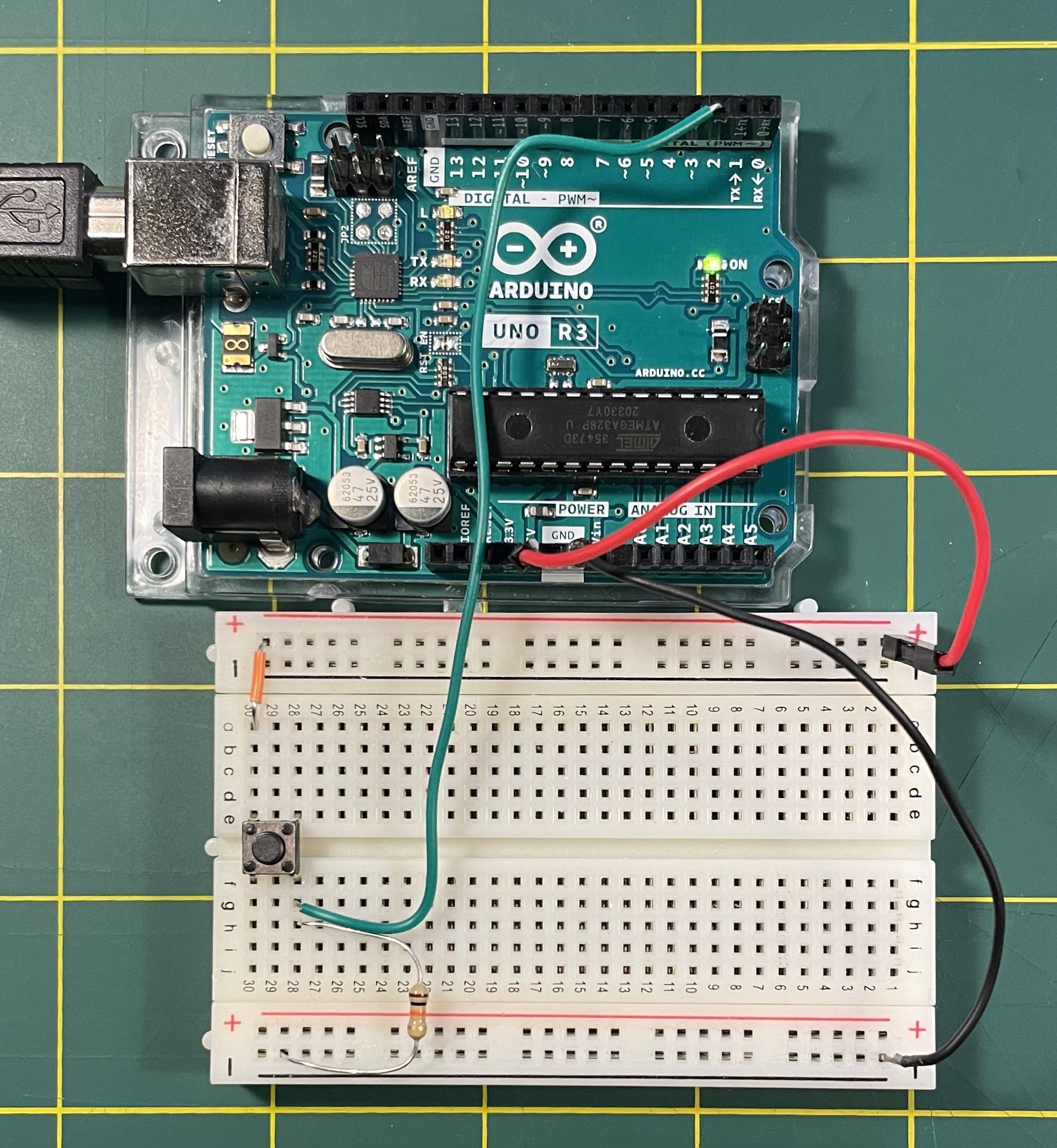
To trace this circuit, note that in the schematic there are three wires coming out of the box representing the Arduino. In Figure 15 you can see these as the red wire connected to 5V, the black wire connected to GND, and the green wire, connected to digital pin 2. In addition to that, I’ve connected the red wire to the “+” rail and the black wire to the “-” rail as a power bus. Then I use the small orange jumper wire to connect my button to “+”. The green wire connects the other side of the button to digital pin 2, and that same location on the breadboard is connected to GND with the 10,000Ω pull-down resister.
Lab notebook task #3: We finally have all the pieces in place to implement a circuit that answers my initial question above. Using this circuit as is (no need to change any wiring), modify your Arduino code so that when the button is pressed the light is off, when the button is released, the light is on. Note that you should only need to change 1-2 words in the entire program. Don’t over-complicated it! Think about this solution to this question in relation to the transistor solution described above. What are some pros and cons of each method?
From digital to analog input
What we’ve just implemented is a digital input component, which we could also refer to as a digital sensor. The button is acting as a digital sensor in the sense that it is either on or off. This value is then being sent in to Arduino, which is then using that value to modify computer program code.
Can we do the same thing but with an analog sensor? What analog sensors have we been using? So far, only the potentiometer.
Open the Arduino program under File > Examples > Analog > AnalogInput and build the circuit diagramed in Figure 16.
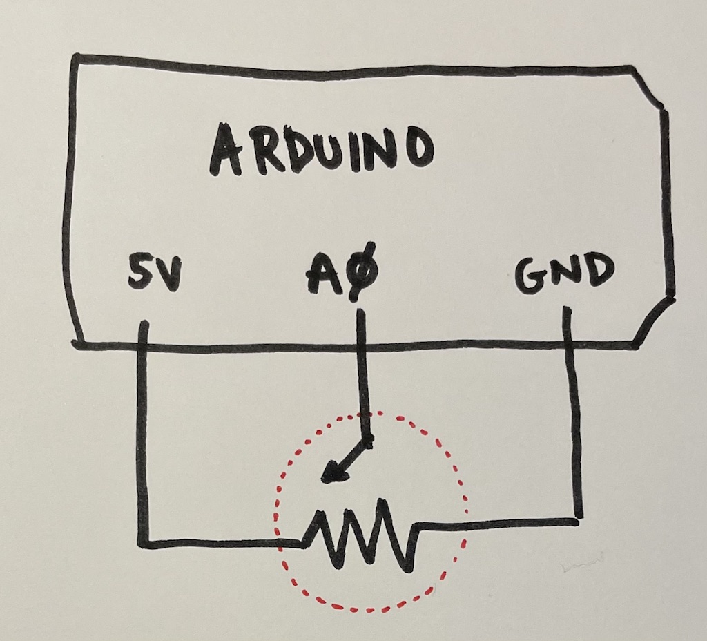
Fig 16. Schematic for potentiometer as analog input. (Click to enlarge.)
Note that the symbol circled in red is the potentiometer, with three connections coming out of it. One side (the left or right, it doesn’t mater which) is connected to 5V, the opposite one (right or left, whichever one you didn’t use for 5V) is connected to GND, and the middle one is connected to analog pin 0, labeled “A0” on the board. Use any extra wires as you need.
Now upload the “AnalogInput” program to your Arduino board. Twisting your potentiometer should adjust the blinking speed of your built-in LED. Notice that the potentiometer has a “built-in” voltage divider in a way. It has three connections, one of which we connect to GROUND, the other to 5V, and the other adjusts in response to how the mechanism is activated. Remember how last week we used only two connections of the potentiometer to create a rheostat – contrast this with our use here of all three connections to create a voltage divider.
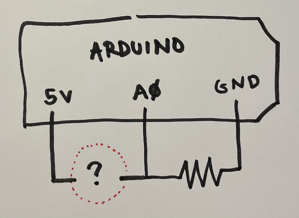
Lab notebook task #4: Leave the “AnalogInput” program installed on your board (no need to modify it or re-upload) and try to build the schematic in Figure 17. For the “?” you can use any element with two connections that produces a variable resistance. But to start, try using the phototransistor that came in your Arduino Kit. See Figure 18 to identify this element. It that looks like a clear LED with a flat top. Note that this component has polarity – make sure to connect the positive side (the longer wire) to 5V.
Lab notebook task #5, challenge: I wrote above that the “?” can be anything with two wires and a variable resistance. Think back to the first homework, in which you used your multimeter to find objects with different resistances. Also think back to last week’s homework where you used stuff around the house to improvise some creative switches. Can you use wires and other materials to improvise an analog sensor in place of the question mark? i.e., something with a variable amount of resistance. Can you test this to change the speed at which your LED is blinking?